7

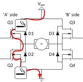
I'm having trouble understanding this concept, here is what the documentation in my microcontroller says about it:

dead bands are defined as the number of PWM clock ticks from the rising or falling edge of the generator’s OutA signal.

Google gives me this diagram, which helps a bit:

enter image description here

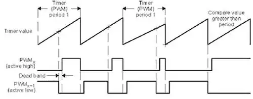
However, I can't see a purpose of doing this. What does it achieve?

tgun926
  • 2,766
  • 12
  • 37
  • 59

1 Answers1

13

When you have an H-bridge it's really nice (as in it prevents fireworks) to have the high side turn off before the low side turns on, and vice versa. The dead time allows sufficient time for "break before make". Without dead time your bridge (or half bridge) can experience something called "shoot through" that is essentially a short across the rails (perhaps they're rectified mains at 400VDC through two transistors in series). At best, this causes unnecessary heating in the output stage, at worst, catastrophic failure.

Lots more at this site.

http://www.modularcircuits.com/blog/articles/h-bridge-secrets/h-bridges-the-basics/

Spehro Pefhany
  • 397,265
  • 22
  • 337
  • 893
  • So it's only useful when you have two PWM outputs (one being inverted) to the same device? Are there any other scenarios where it would be useful? – tgun926 Oct 17 '14 at 10:35
  • 1
    No, I don't think so. It's useful for push-pull type drive. For a half-bridge drive, you can think of this as splitting a single PWM output into two- one for the high side driver and one for the low side driver. Of course it could be done in other ways (with external logic, or some MOSFET drivers have a dead time or adaptive dead time function built-in). – Spehro Pefhany Oct 17 '14 at 11:06
  • So this dead band is between what signals? I think @tgun926 is right you have to have two PWM signals to get use of it. – DannyS Jun 17 '18 at 19:09