You cannot treat the 1/s blocks as just converging to zero. These are integrator blocks as this model is being represented in the s-domain, the integral domain (laplace).
You can however treat the "s" that is part of sL as tending to zero as it represent an inductor. Equally L = 0 so that \$\frac{1}{r + sL}\$ becomes 1/R

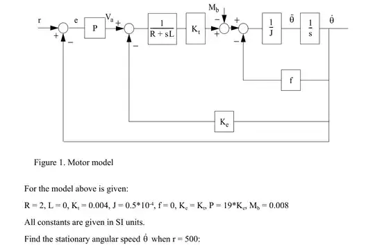
So it is a simple representation of a speed controller.
- You have a speed demand coming in and an error block to provide a speed error.
- This speed error is applied to a proportional gain of 19* the backEMF constant. The output of which is a voltage demand.
This is the end of the speed controller, the rest is the motor model.
- You have an error block that takes the voltage demand & subtracts the "voltage feedback", the terminal voltage of the machine
This provides the forcing voltage.
- A 1/(R+sL) is a 2nd order representation of a machines stator (R+L) and the output is the current that would flow.
- With a stator current generated it is passed through a gain block, with a gain of Kt and the output is then EM-TORQUE.
- Another error block with an input of Mb, at a guess I would say mechanical bearing torque.
- The output is then shaft torque.
- Another error block to provide the ability to load the machine (speed dependent load, maybe a fan?)
- a 1/J block will take a TORQUE and produce ACCELERATION.
- a 1/s block will take this ACCELERATION and integrate it to produce speed.
- This shaft speed is then fed back into the control loops to provide
- speed-dependent backEMF
- speed feedback.
So to analyse this in a steady-state situation:
ASSUME the system has stabilized at no-load speed (as f=0) so the speed feedback = the speed demand = 500.
However... from the additional infomation provided, the controller cannot reach such a speed demand, the added bearing torque has loaded it enough.
For no more acceleration the output of the Mb error block must be zero and thus the output of Kt = Mb = 0.008Nm
So the current must be = 2A
With a stator inductance of 0 & with the sL part generally tending to zero (for steady state) the voltage applied to the terminals needs to be 4V
It has now been reduced to a simple 1st order equation concentrated around the 1st two error blocks. This can be written as
\$(r-\omega)*P = V_a \$
\$ V_{error} = V_a - \omega*K_e \$ Where \$V_{error} = 4\$ from previous calcs.
\$(r - \omega)*P = 4+\omega*k_e\$
\$P*r -4 = \omega*k_e + P*\omega\$
\$(P*r-4)/(k_e+P) = \omega\$
ergo: \$\omega = 425\$