1

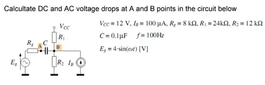
I'm Computer Science student and I'm having a hard time understanding this task:

Exercise

Answer is:

Va for DC = 0V, Va for AC = -1 - 3j

Vb for DC = 4.8V, Vb for AC = 1 - 1j

I have a couple of questions considering this circuit:

  1. What does "voltage at a point" mean. I'm used to calculating node-voltage, voltage over capacitor/resistor etc. but how to find voltage at a point? Should I choose a reference node and calculate node voltage in some way or is it some difference of voltage between a resistor and capacitor?
  2. Is there a difference in calculations between regular DC voltage source and Vcc source?
  3. I planned to use superposition to find required voltages. Is there a possibility of simplifying this circuit before superposition? Is it the best method?

It would be great if someone showed me how to solve it step by step.

Edit: Thank you a lot, now this task seems much clearer. However I'm still having some problems with calculating voltage over A and B for AC.

My solutions for DC matched with answers above, but I don't know if my calculations for AC are wrong or answers are false.

Calculations:

Total impedance: Ztot = R1||R2 + 1/jwC + Rg =>

(24k * 12k)/(24k + 12k) + 1/(j * 100 * 10^-7 * 6.28) + 8k = 16k - j16k[Ohm]

Voltage at B = voltage divider over R1||R2: VB = (R1||R2)/Ztot * Eg =>

8k/(16k - j16k) * 4 = 1 + j [V]

Voltage at A = voltage at B + voltage divider over capacitor: VA =VB + (1/jwC)/Ztot * Eg =>

(1 + j) + (-j16k)/(16k - j16k) * 4 = (1 + j) + (2 - j2) = 3 - j [V]

KVASS
  • 11
  • 1
  • 3

2 Answers2

2
  1. Ground (those flat symbols at the bottom) is the point on your circuit that you'd consider to be 0 volts. Everything else is relative to ground. That means that "voltage at a point" is really "voltage between this point and ground."

  2. \$V_{cc}\$ is just a DC voltage source, so you can treat it the same as any other DC source.

  3. Superposition is a good idea. To simplify the circuit a little,

    • For any DC components, a capacitor looks like an open circuit - you can just rip it out and ignore that it was there.
    • For any AC components, a DC voltage source like \$V_{cc}\$ (which has an AC voltage of \$0\$ V) looks like a connection to ground. Likewise, a DC current source has an AC current of \$0\$ A, so it looks like an open circuit.
Greg d'Eon
  • 3,827
  • 4
  • 24
  • 50
0
  1. "Voltage at a point", means voltage at a node with reference to ground. The ground connections are those little bars at the bottom of the schematic. The voltage at ground is by definition 0 V.
  2. Vcc is simply a constant DC voltage. You can think of it as an unwritten DC voltage source.
  3. Just using superposition is exactly the way to go:

    a. Consider all AC sources, i.e. Eg, to be constant 0. Now solve for the DC voltage at A and B.

    b. Now, return to the original circuit, then set all DC voltages, i.e. \$V_{cc}\$ and \$I_B\$ to be 0, while letting \$E_g\$ alone. Solve for A and B.

The true voltage at point A is the sum of the AC and DC components for A. You solved for the DC component in step (a) and the AC component in step (b).

caveman
  • 1,969
  • 12
  • 12