I am referring to the symbol with +4V next to it. Seems like a voltage source to me. I just haven't seen this anywhere before.
I am referring to the symbol with +4V next to it. Seems like a voltage source to me. I just haven't seen this anywhere before.
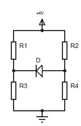
Strictly speaking, it is not a full circuit, but an equivalent full circuit can be easily derived from it, because it has the full information. It has two "labels" (which are not an actual components), which are denoted with the GND symbol (the bottom one) and the triangle symbol (the top one). Both are denoting the voltage levels of the nets they are connected two. The ground is denoting the voltage of 0V (reference potential, to be precise), and the triangle is the denoted (+4V) voltage relative to that reference. The equivalent circuit would look exactly like this one but with a 4V power supply with "+" connected to the triangle, and "-" connected to the GND.
I assume you are referring to the top symbol, the triangle pointing up to "+4V". That is showing that the net is connected to a +4 V supply. The other symbols with "R" designators are resistors. The symbol with the "D" designator is a diode, cathode to the left, anode to the right. This means current can flow thru it right to left but not left to right.
That upwards pointing triangle symbol represents a power terminal in labcenter proteus.
By default in projects the terminal is connected to VCC net (5v) but can easily be connected by the user to any other power rail, even negative ones (referenced to the ground).
Another option if for a user to asign a voltage directly to the terminal by typing a number as a label with a + or - sign in front of the number for positive and negative voltages respectively.
A +4 represents a 4v voltage source referenced to the ground, it's the equivalent of connecting a 4v battery or voltage source between the power terminal and ground.