Something along these lines MAY meet your specification.
I'll not develop the cct fully at this point as eg M1 & M2 may be deemed to be excessive to spec.
If so, what is allowed?
eg are diodes OK - a diode switch could be implemented which is 'unblocked' by high or low output.
Here OA1 +ve output sing has to have Vout > Vhi + Vgsth of M1 and the opposite applies with M2.
Vin connection to IC1-+ input makes this look like negative hysteresis but M1/M2 may invert input polarities depending on how Vhi and Vlo are set. I have not fully thought through what the bounds are on the various voltages or even how they are best switched, but something along these lines looks workable.

simulate this circuit – Schematic created using CircuitLab
Why only one IC?
Being able to use two probably makes life more straightforward.
A diode gated version could look something like this.
Vlimhi and Vlimlo are either fed to point C via diodes D1 or D4 respectively or blocked by input from Vout via diodes D2 and D3.
R3 is a high value resistor shown as fed from Vdd/2 - but call this Vref instead. This resistor is intended to provide diode conduction of D1 and D4 when they are not blocked by Vout. Vref should lie about midway between the high and low limits and could be provided by a divider between them so it can move as they do. D1 & D4 should be Schottky diodes to minimise difference between the input voltages and opamp input. D1 & D2 maybe be silicon or Schottky.
Odds are that the circuit would need a little playing with to optimise it but it should work well enough for many purposes. I my have made some major error in polarity somewhere but hopefully not. Regardless, the principle should be clear enough.
In the circuit the waveforms at A B C D are all the same in polarity and shape but assume different levels as shown by the captions.
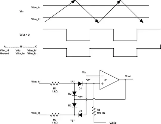
simulate this circuit
Resistor values are nominal.
R1 R2 stop the IC output fighting directly with the control voltages and R3 is intended to be >> R1 or R2 so reference voltages are not greatly diminished by resistor divider.

