3

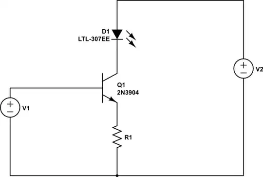
When the base side of the transistor giving a voltage 0 V, across the collector side getting 2.3 V and if give to the base side only voltage 3.0 V, the collector giving voltage 2.9 V. It is not decreasing why?

  • transistor NPN MMBT3904.
  • Resistor 2.2 k.
  • collector voltege 5 V.
  • base Refernce voltege is 3 V

I want to get if 0 V collector side get voltage is 0.2 or 0 V. If 3 V, I want to get 3.02 or 2.90 V.

enter image description here

m.Alin
  • 10,738
  • 19
  • 63
  • 89
Imran B
  • 31
  • 3

2 Answers2

2

You used a transistor as a switch, but made a wrong circuit. The correct circuit is:

transistor as a swicth

R1: This 2k2Ω resistor limits the current flowing into the base of the transistor. You can calculate the current at the base with the assumption base-emitter voltage is about 0.7v.

R2: This 330 Ω resistor limits the current through the LED to prevent the LED from burning out. You can calculate the current at the LED with the assumption drop voltage of the LED is about 1.8v.

Q1: This is a common NPN transistor.

Simply speaking,

  • when V input near 5V, transistor ON, collector voltage near 0v, LED on.
  • when V input near 0V, transistor OFF, collector voltage near 5V, LED off.
Oka
  • 961
  • 4
  • 10
0

Another way of doing this circuit is to use the transistor as a constant current sink.

schematic

simulate this circuit – Schematic created using CircuitLab

V1 is your driving voltage ( like a microcontroller pin). V2 is some voltage source.

With a setup like this, you figure out how much current you want going through the LED (collector) and then set a R1 to set that current.

$$ I_{led} = \frac{V_1 - 0.7}{R_1} $$ $$ R_1 = \frac{V_1 - 0.7}{I_{led}} $$

You'll notice that this circuit uses less components (1 resistor less) and operates the same except you specify the current you want.

efox29
  • 11,955
  • 10
  • 57
  • 104