See info at end re phase control dimmers. Then -
PWM control of phase type dimmer:
To convert a phase control dimmer to a PWM controlled dimmer you could use a comparator to compare the smoothed PWM with a signal which is based on a filtered version of the mains voltage.
In the second circuit below (which uses a TRIAC) the comparator inputs would be filtered PWM and the signal at the C2/R1 junction. When the C2/R1 signal rose higher than the PWM filtered value gthe comparator would fire the TRIAC. As POWM duty cycle increased the brighhtness would decrease. ie The PWM low signal duration would be roughly proportional to brightness.
"Easier" would be to rectify the mains and then modulate a MOSFET with the PWM signal.
eg in the circuit below, the lamp can be fed from rectified mains.

Everything connected to the MOSFET drain and above needs to be scaled up to mains voltage. LAMP goes where DC load is shown. LED indicator as shown is probably unwise. There are other ways to drive an LED indicator.
In place of VR1 smooth PWM and feed to comparator. Or feed PWM direct to MOSFET gate.
The circuit is well described on this webpage.
Changing to a 12V or 24V lamp and using the voltages shown would be safer.
MOSFET as shown is not isolated from mains. An optocoupler drive could be used.
The material below here focuses on TRIAC phase controlled lamp dimmers.
It does NOT address the PWM control question.
Use information above re modifyiing a phase control dimmer circuit by adding a comparator to compare smoothed PWM with mains signal.
Or use a DC lamp circuit as above :-).
Search for
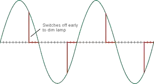
The function that you require is provided by "light dimmers" which are in very common use. The traditional method is to use a TRIAC - an AC electronic switch which can be truned on at any pont in an AC cycle but not turned off again until the next zero crossing of the AC.
Average voltage and thus brightness is controlled by varying the position in each cycle that the TRIAC is fired. This is ca;lled "phase control".
STANDARD WARNING
MAINS VOLTAGES CAN KILL YOU
Dimmers of the sort described below usually have ALL parts effectively at mains voltage.
Build with care and understanding OR don't even start.
CIRCUITS:
Here are many images of TRIAC dimmer circuits with links to the related page in each case.
The diagram below shows a typical TRIAC based dmmer.
Good basic description of the circuiit below is found here

This is functionally the same - has a simple PCB image - no noise suppression components.

Mains driven dimmable LED cpntroller.
Allows LEDs to be driven from mains and dimmed with a standard TRIAC phase control dimmer.
LM3445 TRIA dimmable off line LED controller IC
In stock at Digikey $3.78/1
LM3445 datasheet

LM3445 dimmer youtube discussion - excellent.
Kitset lamp dimmer on ebay - about $US10
ebay dimmer 110 VAC 250 Watt $US10

