1

I'm trying to figure out how to build my own PiSupply as my first electronics project. The schematics of the PiSupply are provided here as a PDF in the zip file, but I've reproduced the schematic to the best of my ability.

My questions:

  1. Why is the normally-connected part of the SPDT switch connected to the capacitor/transistor part of the circuit at all?

  2. Why are there two transistors in the circuit?

  3. Why is there a resistor and ground by the SOFT_OFF?

  4. What's going on with the relay coil being connected with a diode?

The circuit:

CircuitLab Schematic ejpyv9

beerbajay
  • 125
  • 6
  • If you want to build supply for the PI from the GPIO-s, you don't have to reverse engineer the supply on the board. You can find the necessary instructions here, if you want to create board connected to the GPIO-s: https://www.raspberrypi.org/blog/introducing-raspberry-pi-hats/ Details are on GitHub: https://github.com/raspberrypi/hats – Milan Tenk Oct 12 '15 at 17:54
  • @ramez Ah, well, what I actually want to do is build an 18V version of the PiSupply to power the Pi + HifiBerry. Since I'm a total electronics newbie I thought I'd start by understanding an existing device/design. – beerbajay Oct 12 '15 at 17:57
  • I hope you don't plan to output 18V directly to your RPi, do you? – Dmitry Grigoryev Oct 12 '15 at 18:01
  • @DmitryGrigoryev No, the 18V goes into the HifiBerry's power input, which handles the power to the Pi. – beerbajay Oct 12 '15 at 18:02

2 Answers2

4

Why is the normally-connected part of the SPDT switch connected to the capacitor/transistor part of the circuit at all?

To provide initial current to transistor's base, until the RPi gets powered.

Why are there two transistors in the circuit?

Because 1 transistor doesn't amplify the current enough.

Why is there a resistor and ground by the SOFT_OFF?

To pull down that line to 0 V when the button is not pressed.

What's going on with the relay coil being connected with a diode?

To absorb current from relay coil when transistors shut it down.

Dmitry Grigoryev
  • 25,816
  • 5
  • 45
  • 107
  • The spec sheet for the transistors says that they have a gain of 200; when everything is off, there's a 5V potential across the 22K and 10K resistors and the transistors, which I guess means that the current through the resistors is 5V/32K ~= 0.15mA. The first transistor then produces 31.2mA and the second 6.25 amps. Does that sound right? – beerbajay Oct 12 '15 at 20:10
  • Not quite. DC current gain of 200 is given for Ic=2mA, it will be lower for higher currents. Also, the base current is much less than you think: RPi outputs 3.3V and not 5V, and you have to substract the voltage drop on D1, Q2 and Q1, leaving you with about 1V across the resistors. – Dmitry Grigoryev Oct 12 '15 at 20:38
  • Thanks for the clarification. I was using 5V for the pathway with the relay in the normally-closed position. I see that silicon diodes usually have a 0.7V drop and the pair of Q1,Q2 should be 1.3V from the wikipedia page on Darlington transistor. Noob problems :) – beerbajay Oct 12 '15 at 22:40
  • Realistically, the Darlington is pointless in this application, as there is no need for amplification - just use a logic level N-Channel MOSFET. That is a voltage controlled device, as opposed to the BJT which is current controlled. – Kurt E. Clothier Oct 13 '15 at 04:55
  • @KurtE.Clothier a FET with saturation voltage below 3V may be more expensive than 2 BJTs. This is a kit sold in large numbers, so keeping the price down (even by a few cents) may be relevant. – Dmitry Grigoryev Oct 13 '15 at 05:51
  • @DmitryGrigoryev Very True. I'd imagine the cost is the big kicker there. Although, I'd almost always pay a little more up front if it meant savings in the long run. It would take awhile, but power inefficiencies almost always cost more than a slightly cheaper part in the long run. Not always, but most of the time, at least in my experience. – Kurt E. Clothier Oct 13 '15 at 06:20
  • 1
    @KurtE.Clothier For PiSupply folk the "long run" is over once the kit has been sold, so they should not care. As for the end users, I don't think power inefficiency will ever matter (we're talking micro-amperes here, right?), but this second BJT is another point of failure compared to a single FET. Replacing the Darlington pair by a MOSFET is therefore a perfectly valid advice to the OP. – Dmitry Grigoryev Oct 13 '15 at 16:56
4

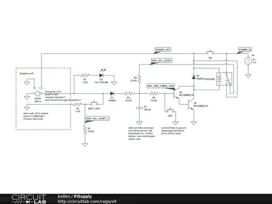
Rather than just answer your questions, I thought I would step through what is actually happening in the circuit to help you understand what is going on.

Let's start with time t = 0, when the Pi is turned off.

Pi Supply time = 0

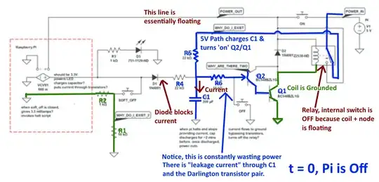
At this time, the relay coil is off, but 5V is still flowing through normally closed switch to C1, the resistors, and the darlington transistors. This current flow through R5 and R6 turns on the base to Q2, which I believe you now know is part of the Darlington Transistor pair, used for increased amplification (although an N channel MOSFET would be more efficient here).

Now, let's see what happens when you press the 'ON' Button at time t = to.

Pi Supply time t = to

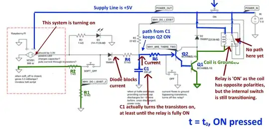
Now, there is a path from the 5V source to the Pi input as well as directly to the top of the relay coil. The capacitor C1 will keep the transistors ON for long enough for the relay coil to full activate, causing the internal switch to move. Note, in this state, there is no path through the relay switch - it is in between states!

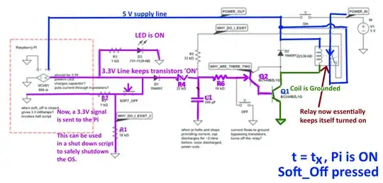
Once the ON button is released, the Pi is fully powered and starts producing its own 3.3V power rail. Let's see what this looks like at time t = tn.

Pi Supply Time = tn

At this time, the relay is keeping itself turned on. The voltage keeping the coil activated is getting there through the relay switch itself! Also note, that now the transistors are kept ON (grounding the coil) by the 3.3V line coming from the Pi. This also illuminates the indicator LED.

The circuit will happily stay in this state as long as the power supply puts out 5V, but what happens when one of the off buttons is pressed? Let's find out! Will call this time t = tx, and the 'Soft_Off' button is pressed.

Pi Supply Time t = tx

This one is really simple. All this does is provide a path for 3.3V to flow through the resistors R1 and R2, overpower the weak pulldown resistor R1. This sends a positive voltage through R2 and into the Pi, which I assume is to be used with a shutdown script to safely shutdown the Pi's OS. R2 is there to limit the current flow into the I/O pin.

Lastly, let's see what happens when the 'OFF' button is pressed at time t = tz.

Pi Supply Time t = tz

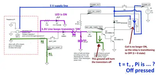
Again, this one is pretty easy to understand. When the 'OFF' button is pressed, a direct path to ground is seen at the base of the transistor Q2, which turns the pair off. This removes the ground from the coil, turning the relay off as well. Again, this is a transitional phase. The relay switch will still be ON for a moment, and the Pi will still be powered. The voltage on the lines will fluctuate until it all settles to the initial state we saw at t = 0 again. This shouldn't matter, as long as you are properly shutting down the Pi (with the soft_off button) before turning the power completely off!

One last point - While Diode D1 is there to simply allow the one-way current to flow when the Pi is powered on (see time t = tn), the Diode D2 is there for protection against voltage spikes from the relay coil. It is called a Flyback, snubber, freewheel, suppressor, or clamp diode (depending upon who you ask). Check out the Wikipedia article!

Kurt E. Clothier
  • 4,439
  • 19
  • 31
  • Excellent write-up. What happens after the Pi powers via its halt script (after soft_off is pressed)? My intuition is that the Pi stops sending 3.3V, but doesn't actually power itself down, the capacitor discharges and eventually stops sending current through the transistor pair which then flips the relay back to its normally-closed state. – beerbajay Oct 13 '15 at 10:18
  • Also, if I was designing this circuit, why would I choose a specific value for my capacitor over another? Is it mainly to control the discharge rate after the pi shuts down? – beerbajay Oct 13 '15 at 11:30
  • @beerbajay, yep C1 and R6 define the time allotted for the RPi to shutdown properly before the power is cut. – Dmitry Grigoryev Oct 13 '15 at 17:06
  • Hmm, if $\tau = RC$ where $R = 10000$ and $C=0.0002$, then $\tau = 2$ seconds, but I got the impression from the PiSupply documentation that it'd take 2 minutes before the power was cut. Did I miss something here? – beerbajay Oct 14 '15 at 04:54
  • Actually, the 3.3V supply works as long as there is 5V present a the Pi input. Hence, even after the Pi "shuts down" there is still a 5V input and a 3.3V output. Hence, the transistors will still be powered. There are some tricks you can do with I/O lines to automatically kill the power, but for this circuit you will have to manually do it using the OFF button. Check out the R PI schematic to see how the internal PS is connected: http://www.rs-online.com/designspark/assets/ds-assets/uploads/knowledge-items/raspberry-pi-model-b-schematics-revision-2/Raspberry-Pi-R2.0-Schematics-Issue2.2_027.pdf – Kurt E. Clothier Oct 14 '15 at 18:03
  • Also, yes, it can take a couple of minutes for the Pi to shutdown. It is running an actual Operating System, so it always takes time for that to finish what it is doing and kill all running processes. The only 100% way to know it has fully shut down is to wait until the activity LED on the Pi is inactive. Even if you powered an LED from an I/O pin using a script, that I/O pin will turn off about 10 seconds before the Pi OS is fully shut down. At least, that's about the time it has taken on mine. – Kurt E. Clothier Oct 14 '15 at 18:06
  • @KurtE.Clothier I checked the PiSupply manual again; it uses pin 8 (GPIO14, TxD) to send the 3.3V. As I've understood it, this is a serial pin, so it'll go low on halt, cutting the current as I speculated above, so you shouldn't have to additionally press the OFF button (this would defeat the purpose of the whole thing anyway). If it's true that the pi stops sending current, are my calculations that power will be cut after 2 seconds correct? – beerbajay Oct 15 '15 at 13:04
  • That is a very interesting (read: dumb) design choice - the Serial port is now unusable. In any case, yes, that GPIO will go LO on halt; however, this will take place a few seconds before OS is 100% shutdown (another reason this is a bad design choice). As far as the calculations go, you are correct. The fall time is 2.2 * Tau, hence 2.2 * 10k * 200u = 2 Seconds. It might be less time than that as the Q2 base current will be too low to keep the transistors saturated. If you are making this, I would use a different GPIO, and increase Tf to 10 seconds. – Kurt E. Clothier Oct 15 '15 at 21:20