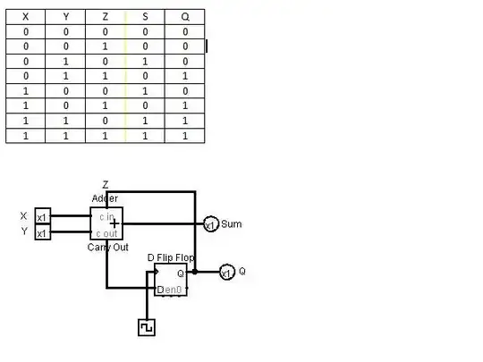
I made a truth table for this sequential circuit, and I wanted to make sure that it is correct. Is this right? The top left is a full adder, and the top right is a D flip-flop.
Asked
Active
Viewed 1,831 times
1 Answers
2
First: let's assume that the truth table values are calculated for the rising edge of the clock. This is sequential logic, and the truth tables requires informations about the previous state; in this case, Z represents Q(i-1).
There are some mistakes in the truth table, but the truth table of the full adder is this:
$$ X+Y+Z=1 \rightarrow Q=0, S=1 $$
$$ X+Y+Z=2 \rightarrow Q=1, S=0 $$
$$ X+Y+Z=3 \rightarrow Q=1, S=1 $$
The flip-flop is used to keep the old carry output until the clock is raised (and to avoid the loop due to the feedback to the carry input), and it doesn't change the truth table as long as you consider the values after the edge.
So, this should be a (clocked) serial adder, because inputing two sequences of bits (starting from the less weighted) after resetting Q, you have at the output S the equivalent bit of their binary sum.
IMPORTANT: You should latch the sum bit because otherwise when you have the rising edge, the sum will be updated with the new value of the carry, so will be valid only until the carry signal is passed through the adder.
In this case, in which the sum bit is not latched, it will assume a value that takes into account the carry of the new operation, and it won't be correct; so the truth table will be like this:
Z  Y  X  |  Q  S
----------------
0  0  0  |  0  0
0  0  1  |  0  1
0  1  0  |  0  1
0  1  1  |  1  1  !
1  0  0  |  0  1
1  0  1  |  1  0
1  1  0  |  1  0
1  1  1  |  1  1
! := It's not the value that an adder would give, because with the clock raising edge, the carry out is brought to Q and sums with X and Y giving again the sum and carry high.
clabacchio
- 13,501
- 4
- 42
- 80
-
I realized that there is small mistake in that schematic, which I think you caught. The sum is supposed to be output as "S", and the carry is fed into the d flip flop not vice-versa. Is that what you were assuming? – David Jan 27 '12 at 14:40
-
I'll do that right now... – David Jan 27 '12 at 14:43
-
I replaced the schematic and the table using the same logic I was using before. I hope this one is easier to read than the last one. – David Jan 27 '12 at 15:08
-
@David I've removed my comments because they were not helpful in understanding the answer. – clabacchio Jan 27 '12 at 15:12
-
If I understand this correctly, if the Z is 1 than that means that the LAST time the D flip flop was run it was one. After the clock is pulsed, it won't be a 1 unless the carry out is a 1. Is that correct? – David Jan 27 '12 at 15:18
-
I think that I'm starting to get it. I'm just confused, when the d flip flop starts off at 1. That means that z will be one, but the next time the clock pulses, since the carry out is a 0, the d flip flop will be 0, making Q and S 0. What is wrong with this logic? – David Jan 27 '12 at 15:30
-
I don't get your logic: the D flip-flop just replicate the input to the output when the clock is raised; the carry-in, (or Z) has the same weight of the other inputs to the full adder. So S and Carry-out are dependent by X,Y and Z without any difference, and Q is Carry-out after the clock is raised. – clabacchio Jan 27 '12 at 15:34
-
I think that I'm missing something. If the Z is a 1 (ie. the d flip flop is 1), then the carry out is 0. If the carry out is 0 then all the inputs turn into a 0 (the next time the clock pulses), since Z is no longer a 1 (since the flip flop is now 0). – David Jan 27 '12 at 15:42
-
@David Why are you saying this? do you know the truth table of the full adder? http://en.wikipedia.org/wiki/Adder_(electronics) – clabacchio Jan 27 '12 at 15:47
-
I get that normally if z were 1 than the sum is 1. However in this case, since there is a clock, the next time the clock pulses the z WILL be 0 (since there was no carry out). – David Jan 27 '12 at 15:52
-
I don't fully get it, but thanks for all your help. I'm guess I'm just confused about how circularity works in circuits. I'm going to try and do some research on it. – David Jan 27 '12 at 16:27
-
@David, the full adder is actually adding 3 things together. It is adding the "Z" net, "X" net, and "Y" net. This is because any carry in must be added just as if you were doing math normally by hand, the carry from the previous digit will be summed. This means that if the Cin is "1" then your C_out will be "1" unless both x and y are 0. binary overflows whenever you get a value greater than or equal to 2, ie (10 or 11). – Kortuk Jan 27 '12 at 16:55
-
@clabacchio, I think you mean on your equations that D will be that state. Q will not change until the next clock transition. – Kortuk Jan 27 '12 at 16:57
-
@Kortuk, what I mean is that if you have x=1, y=1 and Q=0, the input D will be high. So at the rising edge, Q will become high and so also Sum, but the carry should be sum to the next bit of the addition – clabacchio Jan 27 '12 at 19:05
-
@Kortuk If z=1 that means that the (q of the) d flip flop also equals 1. Shouldn't q also equal 1 then? – David Jan 27 '12 at 20:19
-
@David, when designing logic with flip flops you do what is called next state logic. This means the outputs of your flip flops act as inputs to the system, the inputs of flip flops act as outputs. This gives you a truth table taht allows easy mapping of the state progression of gates. – Kortuk Jan 27 '12 at 23:24