3

I have a microcontroller driving a solid-state relay to switch an LED lightbulb (the household type).

EDIT: added circuit (maybe it addresses Andy aka's comment?). PB0 is the bit 0 of output port B of the microcontroller (AVR tiny25)

schematic

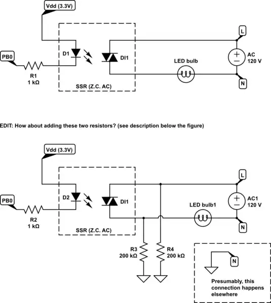
simulate this circuit – Schematic created using CircuitLab

ADDITIONAL EDIT ABOUT ADDED FIGURE ABOVE:

Related to winny's comment/solution --- since I can't (in general) connect a resistor in parallel to a lightbulb (it would require hacking into the lamp or fixture), I could take advantage of the fact that GND (household GND) and N (neutral) are connected, and place those two resistors (only one is necessary, but placing two makes the contacts of the SSR output interchangeable). Does this work?

--- END OF EDIT ---

I thought zero-crossing was a good idea, so I'm using the IXYS CPC1965Y. It's not working: when I switch it on, the lightbulb gives out a flash (like a photographic camera flash) every 3 or 3.5 seconds.

It's not the circuit --- I replace the LED lightbulb with an incandescent lightbulb and it works perfectly ok. Also, a curious detail is that I first had gotten the CPC1976Y (2A, instead of 1A) and tried with that one, and it was working ok. (then, digikey ran out of stock, so I got the 1965Y assuming that functionality would be identical)

The manual (both the 1965Y and the 1976Y) talks about low power factor; specifically, it lists 0.25 as the PF required for guaranteed turn-on, and a footnote says: "snubber circuits may be required at low power factors". However, it does not say anything about what the snubber circuit should look like.

I think the notion of PF would not apply to an LED lightbulb in the strict sense, since it is non-linear; but I guess the issue for the SSR is the same.

Will I really need to switch to a non-ZC SSR? (they're more expensive, surprisingly enough :-( )

Any suggestions on how to make it work with the ZC SSR?

Thanks!

Cal-linux
  • 2,123
  • 2
  • 22
  • 40
  • Is your circuit the industry standard one? – Andy aka Oct 27 '16 at 14:17
  • 1
    Several similarities to http://electronics.stackexchange.com/questions/263966/led-bulb-flicker-rate-of-50-hz-or-more/263968, but your bulb seems to have UVLO protection, hence the difference in frequency. Does it help at add load in paralell to satisfy the minimum holding current? – winny Oct 27 '16 at 14:35
  • @Andyaka: not sure whether you're asking about my circuit or the circuit inside the LED lightbulb --- I edited my post to add the schematic of what I did. – Cal-linux Oct 27 '16 at 15:24
  • Ah that's better. – Andy aka Oct 27 '16 at 16:27
  • @winny: yes, it does work. Though the datasheet specifies a minimum load current of 5mA, with as much as a 200k resistor in parallel with the lightbulb, it works --- the microcontroller turns on and off the lightbulb. – Cal-linux Oct 27 '16 at 16:30
  • There you have it! If you measure the voltage and current waveform on your oscilloscope as you decrese the load resistance, you will see the cut waveform appearing where you no longer draw enough current to hold the triac. Should I add it as an answer? – winny Oct 27 '16 at 17:00
  • I just edited the post (the schematic) to follow-up on this issue and the solution you suggested. Do feel free to comment on it or post an answer. Thanks! – Cal-linux Oct 27 '16 at 18:41
  • You can not place a resistor from phase output of your dimmer to ground without tripping your RCB. You can however connect it to any neutral. So skip R4 and connect R3 to neutral. Also, add @ before the username or he/she won't be notified. – winny Dec 05 '16 at 20:26
  • @winny: not sure what you mean by "tripping your RCB" (in fact, I'm not sure why you say I cannot place a resistor from the L to GND. The wall boxes have GND, and usually, things are connected so that the L always makes it to the box, in case one needs to install something that requires power (in which case the power is drawn from the pin L and returning through GND). Can you clarify? – Cal-linux Dec 06 '16 at 00:33
  • @winny -- I guess RCB refers to "residual current braker"? (I couldn't find it at first, as the typical acronym seems to be RCD -- Residual Current Device). I wonder whether these are always installed, or is it just in specific lines in the house. I ask because I did a temporary connection to test, and I went down to 20k to ensure a 6mA current, above the required holding current of the SSR. It worked (including the fact that it didn't trip any disconnection device). Can someone shed some light? – Cal-linux Dec 06 '16 at 01:28

1 Answers1

1

Snubbers are generally capacitors in series with a resistor ( which absorbes the transient energy) You could try a 240V ac X rated 0.47uF capacitor in series witha 47 ohm 1/2 watt resistor across the LED just to see if that makes a difference. Remeber PF is is defined not only a function of displacement between voltage and current ( as per an inductive or capacitive loads ) but also of harmonic origin, as per non linear devices. For the LED the distortion may occur around the zero crossing point of the AC waveform due to the LEDs V/I characteristic below a few volts - thinking maybe that is the reason for that type of zero crossing SSR not triggering reliably ? The capacitor / resistor combination will provide an element of inphase current / voltage which will help trigger the SSR reliably.

spanners
  • 11
  • 2