I want to make my own alarm system, I put a long cable from my alarm and a sensor, if the sensor's cable is cut, the circuit change it's logic state, and then I read it. But the problem is that the long cable has it's own resistance and other problem I have is the possible induction.
-
What do you perceive as a problem with the cable's resistance and inductance? – Majenko Jul 15 '17 at 17:16
-
I have a raspberry reading the pin state, the cable goes inside the wall with more cables, so induction may be a problem for my raspberry and get destroyed because of different AC and DC in the cables. – Sebastian Tare B. Jul 15 '17 at 17:23
2 Answers
Most alarm systems actually use a very simple system: If the input pins are connected together (or the input is connected to ground, or whatever scheme you choose) then the sensor is considered "inactive". If the sensor activates, or the wire is cut, the connection is taken open circuit and it is considered "active".
For instance:

simulate this circuit – Schematic created using CircuitLab
As long as the voltage at INPUT is pulled below the low logic input level (\$V_{IL}\$) the alarm is off. As soon as it rises above the logic high level (\$V_{IH}\$) the alarm sounds. If you have particularly lossy cable or it's in a very noisy environment you can adjust R1 to compensate.
For extra security you could make your sensor more active and have a self test mode. Add a fourth "test" wire that triggers a test, the result of which is to activate the sensor as if it were triggering the alarm - however your software knows to not sound the alarm, instead to just note that the sensor is functioning properly:

- 56,223
- 9
- 105
- 189
-
But reducing R1 that would cause the system to detect too many False Positives – Sebastian Tare B. Jul 15 '17 at 17:34
-
R1 and the wire form a simple resistive divider. Adjust R1 so that the voltage levels present at INPUT are correct for the device doing the reading. If there is too much noise reducing R1 will help to reduce the effect of that noise. If the resistance of the wire is too high increasing R1 will keep the voltage low. However the resistance of the wire would have to be significant to make you need to change that resistance. – Majenko Jul 15 '17 at 17:37
-
The smaller R1 is the harder it is for noise to pull the voltage down below $V_{IL}$. The larger R1 the easier it is for the closed loop of the wire to pull it down below $V_{IL}$. – Majenko Jul 15 '17 at 17:38
-
1Given a typical $0.3V_{CC}$ value of $V_{IL}$ you would need a cable resistance of about 2KΩ for it to become an issue. That's either really shite cable or your sensor is in the next town. – Majenko Jul 15 '17 at 17:40
-
-
1It is also common to protect your inputs with TVS diodes or even optoisolators. – Majenko Jul 15 '17 at 17:45
Your concern about wall-wiring inducing errors is correct. Microwave ovens are the worst trash generators in a home, from what some home-wiring (power and entertainment, combined) installers have told me; they make big bucks by taking full responsibility for expensive homes that demand the computer/music/video performance be flawless, even with lots of "electric power" appliances functioning. Microwave oven power supplies, rectifying 2,000 volts across a few diode junctions, generate enormous rates-of-change-of-current.
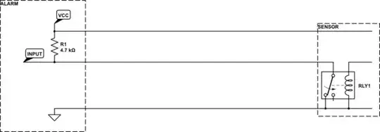
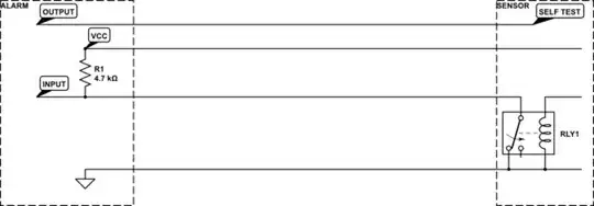
For your alarm system, insert a low-pass filter right at the sensor.
I'd split up the resistor; use half at far end of wire, and half in the RC filter located directly at the sensor.
2kohm and 10uF, at the sensor.
==========================
How bad can the induced voltage be? Consider that 2,000 watts being 2,000 volts and 1 amp, being rectified. How fast do the diodes turn on?
The dV/dT of 2,000 volts at 60Hz is 2,000 * 377radians/second or 800,000 volts per second. That will turn on a 0.026 volt diode property in 0.026/800,000 = less than 100 nanoSeconds. We'll assume the power transformer has winding bandwidth to allow 100 nanosecond pulses to pass. (big assumption).
Thus our rate-of-change-of-current is 1 amp in 100 nanoseconds.
If the power wiring runs 10 meters along a sensitive wire (and there is lots of separation between PowerHot and PowerRTN), then this formula can be used.
Vinduce = [MU0 * MUr * area/(2*pi*Distance)] * dI/dT or Vinduce = 2e-7 * (0 meters * 1cm)/ 1cm * 10^7 amp/second Vinduce = 2e-7 * 10 * 10^7 Vinduce = 10 volts
- 34,253
- 2
- 19
- 48
-
You are right, and i dont want my raspberry get destroyed by induction, i would like to mark your answer as useful but i don't have enough points, also i think i will use an Optocoupler – Sebastian Tare B. Jul 15 '17 at 17:51
