0

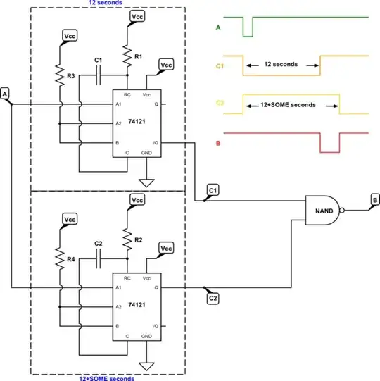
In my design, say there are 2 pins A and B.

Now I want to implement circuit in such a way that B is initially high , but when A goes low, after 12 seconds B will go low for short duration and again will become 1. Is there any circuit which I can implement.

I tried below Monostable multivibrator as timer using IC555, but issue is that initially B is low as per configuration. 555 as Monostable

Required signals as below:

Signals

Can someone help me and suggest? Thanks in advance.

Electroholic
  • 739
  • 10
  • 34
  • If both of these signals are going into GPIO's configured as inputs, could you do this in software instead? The pin formerly called "B" could then be used for something else entirely. – AaronD Aug 10 '17 at 06:51
  • You are requesting a circuit to be designed. Does the circuit use A as an input only? You want a circuit that reacts to A going low, is that correct? Or do you want a circuit that drives A low? – user57037 Aug 10 '17 at 06:54
  • Due to some reason , I have to do it using hardware. "A" going low and then after 12 sec, B goes low are two separate events and has different meanings in hardware. – Electroholic Aug 10 '17 at 06:54
  • Basically, operation is when A is low ADC starts and after 12 seconds B goes low indicating ADC reading done. And " B low " event have to do using hardware only. ( A and B input always ) – Electroholic Aug 10 '17 at 06:57
  • I'm not convinced yet that it must be in hardware. Is the ADC in the same chip that reads these inputs? If so, then one or both could actually be software-controlled outputs, if needed externally at all. Regardless though, the "done" signal really should be connected to the thing that is actually done, not based on a timer. – AaronD Aug 10 '17 at 07:03
  • As for taking 12 seconds for an ADC read, that's like forever! I suspect you've misinterpreted something or you have a really rare ADC. – AaronD Aug 10 '17 at 07:04
  • ADC is external interfaced with MCU and A and B connected to MCU (not ADC) ... Basically it's liquid flow from tubing and for 12 seconds liquid with particles flows , No of particles calculated during 12 seconds because particle block tube and voltage change to ADC and this continues for 12 seconds. – Electroholic Aug 10 '17 at 07:07
  • Sounds like two 74121 (or one MC14528B) plus an and-gate. Roughly. Why not that? – jonk Aug 10 '17 at 07:11
  • @ Jonk, can you explain a bit what you are suggesting.Thanks. – Electroholic Aug 10 '17 at 07:15
  • Oh! So it's not an Analog to Digital Converter at all, according to the standard definition, but a pulse counter over a fixed time interval. That really needs to be edited into the question. – AaronD Aug 10 '17 at 07:16
  • I still say it can be done better in software. Skip the external "ADC" entirely and run the pulses directly to the external clock pin of one of the MCU's timer/counters. In software, clear the timer/counter, forget about it for your time interval (12 seconds as stated), then read it. If your MCU has an internal analog comparator with adjustable threshold that can then clock a timer/counter, that's even better. – AaronD Aug 10 '17 at 07:21
  • Dear AaronD , Thanks for your reply. I agree, but due to some reasons I can't change existing software and hence needs to be with H/W only. – Electroholic Aug 10 '17 at 07:23
  • 1
    @Electroholic I can't tell for sure from your description, but it sounds like you are being *directed* to use a hardware solution, where there is a falling edge (A) triggering a delayed, low-going pulse output on B. In short the circuit has one input (A), one output (B), and power and ground. Is that it? – jonk Aug 10 '17 at 07:24
  • @ Jonk you are right. – Electroholic Aug 10 '17 at 07:25
  • 1
    @Electroholic Then it's just two 74121's and a gate. Sheesh. – jonk Aug 10 '17 at 07:25
  • 1
    @Electroholic Each '121 has $Q$ and $\overline{Q}$ outputs, which makes this very easy. Wire one ($U_1$) of them for 12 seconds. The other ($U_2$) is wired for 12 seconds plus your "short duration." Both wired to trigger on the falling edge of A. Wire $U_1$'s $\overline{Q}$ output together with $U_2$'s $Q$ output to the inputs of a NAND gate. The output of the NAND is B. (If I didn't get a polarity wrong.) – jonk Aug 10 '17 at 07:35
  • 2
    I think the problem definition, as understood by us, has changed enough in the comments from the original question that the question really needs to be updated. @Electroholic, can you please do that? Most notably, the GPIO is a red herring and should be removed, and the H/W requirement coming from someone else is important to avoid insistence on an X-Y problem, as I did. Preferably include who that requirement comes from as well, to give it that much more credibility. Then jonk can offer an answer that actually makes sense for the question. – AaronD Aug 10 '17 at 07:44
  • Thanks @ AaronD for concern. @Jonk Can you post this as answer with rough schematics to have better insight. – Electroholic Aug 10 '17 at 08:14
  • 1
    If all that is needed to invert the signal pulse from the 555, use a transistor. Your schematic itself looks fine (though you may need to add a small restistor between pins 6 and 7 to get a somewhat wider pulse) – JvO Aug 10 '17 at 08:49
  • 1
    @Electroholic this question is really similar to this one. – Harry Svensson Aug 10 '17 at 12:41

2 Answers2

1

You could use a Schmitt-Trigger with an RC-LP on it's input and two different resistors for charging and discharging. If Input A goes low, C1 will be discharged via R1. Use a time constant to create 12s delay till the Schmitt-Trigger goes low. R2 determines the time it takes the output to go high again, after A went high.

enter image description here

Alternatively, you could obviously use a small µC like an ATtiny. This would give you a lot more flexibility.

jusaca
  • 9,599
  • 4
  • 38
  • 62
1

As follows below:

schematic

simulate this circuit – Schematic created using CircuitLab

You need to arrange \$C_1\$ and \$R_1\$ so that you get 12 seconds out of the top 74121. You need to arrange \$C_2\$ and \$R_2\$ so that you get 12 seconds, plus some extra time you need, out of the bottom 74121. \$R_3\$ and \$R_4\$ are just there to tie some inputs high. You can use something like \$4.7\:\textrm{k}\Omega\$ if these are 74LS121 types. Use what's appropriate if you use some other device family.

I didn't specify any of the pins. But you have labels and should be able to work that out.

jonk
  • 77,876
  • 6
  • 77
  • 188