2

Which equation defines maximum current sink by Q1 in this circuit ? Which equation define maximum voltage at V2 at which Q1 enter linear mode of operation ( f.e. VCE ~ 0.5V) ?

schematic

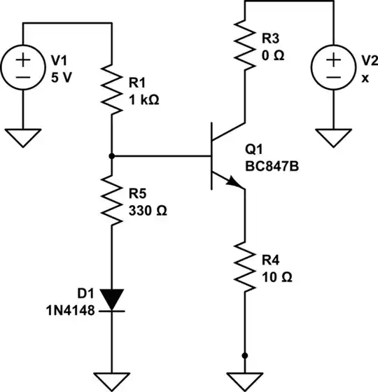
simulate this circuit – Schematic created using CircuitLab

If I consider circuit without the resistor and voltage at collector I can write:

Ic ~ Ie= Ve/R4

When I ignore base current then I get :

Ve = Vb - Ube = R1/(R1+R5)*(5V - UfD1) +UfD1 -Ube

Then with first equation I get:

Ie Re = R1/(R1+R5)(5V - UfD1) +UfD1 -Ube

How to solve these equation in order to get value of sink current by current source ?


doodgraver
  • 41
  • 1
  • 4
  • What do you think it is? Show us where you're stuck. – Harry Svensson Dec 12 '17 at 18:21
  • Can you provide any of your thinking, at all? Or are you drawing a complete blank on how to approach this? – jonk Dec 12 '17 at 19:57
  • 1
    You can replace your $R_1$ and $R_5$ divider with a Thevenin source and resistance. The Thevenin voltage source and resistance would be: $V_{TH}=\left( \frac{V_1}{R_1} + \frac{V_{D_1}}{R_5} \right) \cdot \left( R_1\mid\mid R_5\right)$ and $R_{TH}=R_1\mid\mid R_5$. From that and $V_{BE}$ and $R_4$, you should be able to work out the base and emitter currents (assuming an active mode and not saturated.) Using $I_C\approx I_E$, you should get close I think. – jonk Dec 13 '17 at 10:20

0 Answers0