I need help to build a simple converter to match a 75 ohm feed line to a 50 ohm antenna. Please help :-(
Asked
Active
Viewed 2.4k times
3
-
1Frequency? Power? – Leon Heller Jul 20 '12 at 10:26
-
1Transmitter?, Receiver?, Transceiver? Frequency midpoint?, range of frequencies? ...? A full description of what you are trying to do and with what will help muchly. – Russell McMahon Jul 20 '12 at 12:43
-
Is this part of the function that a Balun is designed to satisfy? – vicatcu Jul 20 '12 at 14:48
-
@vicatcu: Baluns aren't really impedance matching devices. The ideal balun looks like it's not there for differential mode signals. Baluns in RF are usually for converting between single ended and differential signals. For example, a transmitter may have a ground-referenced output and the feed to the antenna could be coax with outer conductor grounded, but a self-contained antenna wants to see both lines equal. A balun at the antenna feed points solves this problem. – Olin Lathrop Jul 20 '12 at 15:21
-
We need more information to help you. This question is going to be closed until you can update it. – Kortuk Jul 20 '12 at 15:30
2 Answers
5
- Use a transformer. At frequencies where 50 versus 75 Ohm impedance matters, it can be quite small. A few turns for each side around a ferrite is probably good enough. The impedance ratio is the square of the turns ratio. One problem with this method is that there will be some loss, and you have to be careful your core (ferrite usually) works at the intended frequency. There are quite a few flavors of "ferrite".
- Look up something called a Smith Chart. It is a graphical means to give you values of reactive components to add to essentially change impedance. It's not intended for exactly this application, but it might give you some guidance. The theory and proper usage of a Smith Chart could fill a whole book, so I'll leave you mostly with the search term.
The basic concept is that a network (usually just two or three) inductors and capacitors between two signals can change the apparent impedance of one signal as seen by the other. The advantage is that this method can be low loss, usually less loss than a transformer. The Smith chart is a graphical way to arrive at the component value, which can be quite complex mathematically. This is usually used at the feed point of a antenna so that the antenna looks just resistive and with the desired resistance. The downside is that this only works at a specific frequency. If your impedance matching has to work over a reasonable frequency range, then adding some capacitors and inductors won't work, and the Smith Chart method of determining them is unapplicable.
Olin Lathrop
- 313,258
- 36
- 434
- 925
-
It wasn't me, but I can imagine she may have doubts about the usefulness of Smith here. I think the transformer is the solution. – stevenvh Jul 20 '12 at 14:25
-
@stevenvh: It is possible to impedance match two feeds at a particular frequency by adding a network of inductors and capacitors in between. A Smith chart helps you figure out what the values would be, but it's not the easiest thing to use for this purpose. I agree though that a transformer is the simpler solution, so I'll flip the order of the answers around. – Olin Lathrop Jul 20 '12 at 14:29
-
" it's not the easiest thing to use for this purpose": that's more or less what I meant. Switching the two is a good idea. – stevenvh Jul 20 '12 at 14:33
-
how much loss? what if it is a 100W Ham wanting to use 50Ω Ant. with surplus 75Ω cable or a microwave repeater using 75Ω gas filled hardline to 50Ω dish? just use any transformer? – Tony Stewart EE75 Jul 20 '12 at 14:37
-
@stevenvh A smith chart is definitely applicable; it is used to calculate where to add a stub (and of what length) to feed lines to minimize VSWR. VSWR is definitively caused by impedence mismatch. From there its a matter of tuning and measuring. QED. – vicatcu Jul 20 '12 at 14:52
-
1@Tony: Of course there are lots of details about designing or chosing a transformer. Any answer has to stop somewhere. Considering the very limited information the OP has supplied, I think I've told him enough to start with. We don't even know if this is a fixed frequency or what power level. More detail has diminishing returns since it could easily not be applicable to the actual problem. – Olin Lathrop Jul 20 '12 at 14:54
-
I looked up his profile. He bought an antenna sales company in South Africa for 2way use. He sells in many bands of 50Ω antenna rated @ many power levels. I think he wants a general solution like mine. Thats why I gave the calculator for the general solution of 1/12 λ 50Ω & 75Ω impedance adapters and the Transmission Line Calculator with all the std coax types with line vs f loss built in. So no searching coax specs needed. I feel the - points on my answer reflect the lack of awareness of the reader, not the asker.. who is certainly aware.... but thats no problem if my answer mismatches them – Tony Stewart EE75 Jul 20 '12 at 15:03
-
this is a case of where a simple question begs a complex answer by other helpers who know something about RF, which is why I offered a simple calc solution to help him.. because I know he sells Antenna to users who use 75Ω coax and cant afford 50Ω coax. So Smith charts and baluns are fine in theory but not in practise. It is a practical solution he wants. However I dont expect any points from those who dont know the difference in RF practical experience and theoretical experience. I have designed about 6 different antennae for commercial use and tested many more. – Tony Stewart EE75 Jul 20 '12 at 15:28
-
1@Tony - the answer is not just for the benefit of the asker, it is also for those who come later. Your initial answer left a lot to be implied, and would be of no help to anyone who wants to learn about such things, which is probably the reason for the downvotes. Discussion of how/why it works, pros/cons vs other solutions, why matching is important, etc, would be more useful. – Oli Glaser Jul 20 '12 at 16:33
0
The Twelfth-Wave Transformer is often a more convenient alternative to the more well-known quarter-wave transformer. It has been around for at least 50 yrs, so I must point out to my less RF experienced colleagues that Hams have been using this to match cheap 75 Ohm feed line to standard 50 Ohm antenna for a long time. The theory is less useful to helping build this than the design tool offered previous in above answer.
This design tool can be applied to any frequency of choice and any coax. preferably large diameter cheap solid coax. surplus or scrap from the cable TV industry known as "hardline" in RF circles, such as gas filled solid coax or teflon filled solid coax.
My diligence indicates the requester has purchased a company in 2005 that sells RF antenna suitable for two way communication over a wide variety of application bands and power levels so choosing an inductor or a balun is not a trivial task.
I proposed using a line loss calculator to match hardline coax to feed a 50Ω antenna is an easier task with this calculator, now it seems other helpers need justification.
Given: Feed impedance line of 75Ω of unknown length, unknown source impedance and antenna of 50Ω for a rated power level and frequency range.
May I refer to the theory in Princeton's University paper, rather than plagiarise, but in short;
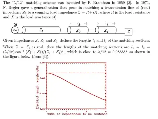
Conclusion:
Choose Coax and calculate 1/12 λ of 50Ω coax. and 1/12 λ of 75Ω coax. for chosen frequency.. This works from DC to 1.5 x center F chosen. These two cables will transform the impedance for maximal power transfer. Choose the lowest loss cable you have avail. and best connectors to achieve < 0.1dB loss for these short lengths.
Convenient calculator: http://vk1od.net/calc/tl/tllc.php#NoteModellingLoss Choose F, coax , 50 Ω load 1/12 λ option enter 0.083333 [wavelength], then calculate. Repeat for both 50Ω & 75Ω coax choosing type of coax as 1st entry.
Tony Stewart EE75
- 1
- 3
- 54
- 185
-
4
-
9How can the answer to "How do I build an impedance converter" be "Choose a middle of range frequency" ? – MikeJ-UK Jul 20 '12 at 10:20
-
Is this a forum for hobbyists or EE's who understand theory. This tool is a design aid. It is as accurate as your inputs. Cable models are precisely simulated. – Tony Stewart EE75 Jul 20 '12 at 11:17
-
4@Tony - he might not even have a cable. His 75 ohm driver may be on the same board where the 50 ohm antenna will be connected. – stevenvh Jul 20 '12 at 12:08
-
5@Tony - unless I'm very much mistaken, it's a forum for both professionals and hobbyists. – Oli Glaser Jul 20 '12 at 13:20
-
May I point out the obvious assumption is that HAMs use 50Ω equipment at both ends but prefer to use lower cost 75Ω feed lines. The 1/12 wavelength impedance matching design is better suited than the 1/4 wavelength design and this design tool is best suited to choose cable and length for any band and any 50Ω antenna and any 75Ω coax with standard curves included in the tool. Just pick the standard coax you prefer like RG-6, enter F nom., enter 0.083333 {1/12}, select [wavelength] and Calculate.. YOu want proof? I can get but that wont help. It is a general solution. He sells RF ant. – Tony Stewart EE75 Jul 20 '12 at 14:18
-
1Sad example of people downvoting a widely used solution outside their experience. – Chris Stratton Jul 20 '12 at 17:03
-
-
3@Tony: it's a forum for people interested in electronic design, regardless of experience level. – Chris Laplante Jul 20 '12 at 19:12
-
-
Well this user is clearly interested in RF design of impedance matching solutions for antennae. What is wrong here? misunderstood reasons, false assumptions ? Mod error? – Tony Stewart EE75 Jul 20 '12 at 20:10
-
1It was closed because the OP didn't provide the requested clarifications and details in a timely manner. If they add the details it will be reopened. – Chris Laplante Jul 20 '12 at 21:50
-
Assuming he is not too embarrassed by all the bad assumptions and trouble it caused judging by the reactions. But you are right. – Tony Stewart EE75 Jul 20 '12 at 22:16
-
2@ChrisStratton Check the revision history. His original answer was unsuitable. He has made a significant edit, practically replacing his original sentence with something that may pass for a valid solution. – W5VO Jul 21 '12 at 01:52