I don't think you can do quite what you specified with only one relay.
If you are prepared to modify your requirements so that the circuit is reset when the ignition is turned off (rather than off and back on again) then the solution is simple.

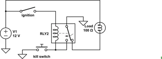
simulate this circuit – Schematic created using CircuitLab
Figure 1. The modified circuit with all switching in positive lines.
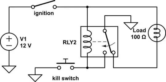
simulate this circuit
Figure 2. By moving the load positive to bypass the ignition switch the OP's circuit timing and operation will match that of Figure 1.

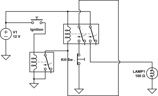
simulate this circuit
Figure 3. A capacitive "kick" circuit and latch.
How it works:
- When the ignition is turned on both sides of C1 rise to +12 V. C1 is sized to provide enough energy to energise the relay.
- The relay contact will then maintain power to the coil and switch on the load.
- If KILL is pressed the relay will be de-energised. Note that since C1 has been charged via the latch circuit that KILL will have to be held for long enough for the relay to drop out. The delay is shown in the timing diagram. This 'feature' may be enough to make this an unsuitable solution.
- D1 prevents the coil energising on a negative going pulse when the ignition is turned off.
For a coil resistance of R a rough idea of the time delay is give by \$ \tau = RC \$. This will need to be at least as long as the pick-time response of the relay.
if I do not press the kill switch my load will also stop having voltage once my ignition is off..... the load will have no power when the ignition switch is off, regardless of the kill switch – jsotola Jun 11 '18 at 16:49