I have a LED candle that runs on two AA batteries which total 3 V. It already has remote. I want that 3 V output to turn on a 12 V battery supply to a LED array.
I am trying to use an NPN transistor for this: am I doing right? What else can I use?
Bruno's circuit uses a FET, which can also be used, but I'll give you an answer for the BJT (Biploar Junction Transistor) too.

First the NPN, at the left. You supply 3 V to base resistor R2. Since the base will be at 0.7 V (the base-emitter junction acts as a diode) you'll have a base current of 2.3 mA. The transistor's collector current will be a multiple of that. For a general purpose transistor the current gain (\$h_{FE}\$) is typically around 100, but will decrease for a transistor in saturation. The 2.3 mA base current will be enough to give you 20 mA collector current though.
R1 is needed to limit the LED current, you'll always need it if you supply LEDs with a voltage source. The value depends on the LEDs' voltgae drop. I've calculated with 2 V per LED, then for 2 LEDs you have 8 V across the resistor. Apply Ohm's Law: R = V/I, then for 20 mA you want a 390 Ω resistor. (actually 400 Ω but 390 is a common E12 value, while 400 isn't).
For the FET's R3 the same holds, so also 390 Ω. A FET is controlled by voltage instead of current, and you'll need a logic level gate FET to be sure it switches on at 3 V. R4 is not always required, but limits the short current peak during switching; the gate forms a capacitance and microcontrollers and other logic doesn't like capacitive loads. R5 prevents that the gate would be floating if it wouldn't be driven.
In this situation I would use a N type FET. I had troubles before controlling loads supplied with a voltage higher than the one applied on the base on NPN transistors. (But maybe is just me :)
The circuit will look something like this:
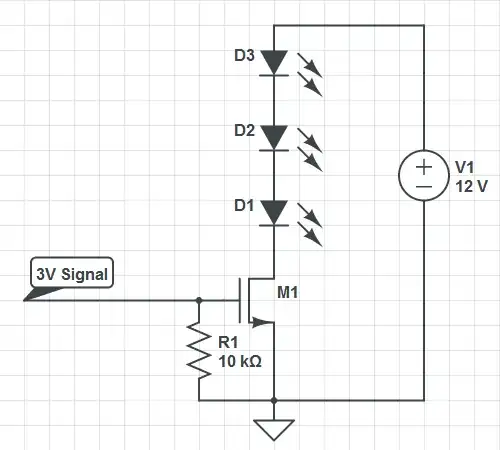
You can use any FET provided that is supports the voltage and current needed for your load.
R1 on the gate of the FET will assure that is stays off when no voltage is applied on it's gate.
For a NPN configuration you will need something like this:
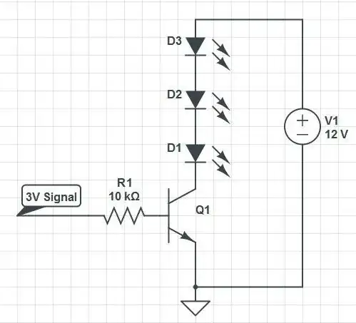
You can use any transistor provided that is supports the voltage and current needed for your load.