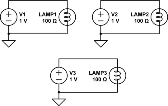
For kids, no gnd symbols are used until it is understood that GND in electronics just means a 0V reference to other local voltages.
To an electrician, “Ground” also means a 0V reference but with AC grid voltages, might also imply “earth bonded” with some low but in practice, never zero Ohms impedance. Also at the same time all voltage sources are never zero Ohms except in theory or ideal models as everything has some nonzero resistance, even any length of wire!
============
Schematics need to consider the standard practices of intended reader using either Corporate, Industry, Academic or global standards such as IEEE, IPC, NEMA, IEC etc.
You must realize that schematics need to communicate sufficient information for the intended purpose and are also called “Logic diagrams” .
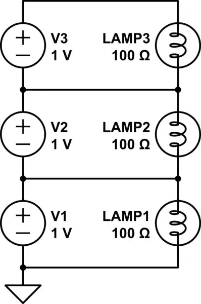
It may be logical to simplify a schematic to show the voltage sources are ideal for simple academic purpose or real such as floating grounds, analog grounds, DC power grounds or AC Earth Bonded grounds, or a chassis ground or an RF ground or optically isolated ground , so there are many ground symbols to choose from. There are star or radial distributed grounds, daisy chained grounds and ground planes. Each are not identical so different symbols may be chosen consistent to your intent or specify needs. E.g. to indicate they are floating sources with an insulation voltage limit, or just a floating source with a “DC supply” and “Return” with an indication of polarity like Vdd,Vss or V+,V-.
But as long as you remember Schematics as just simple “Logic Diagrams” for ease of understanding and never reflect the actual “real life” Impedances unless it is critical to performance, then this must also be documented, by a system or higher level drawing to show interconnections. this includes showing decoupling capacitors, and notes on placement.
Even the Schematic Tool used on this site has 3 different Gnd symbols , but in your case, you wish to indicate they are floating, but have no test points labelled for documents.
My suggestion is always design for test ability and readability, so include labels and test pin points.
In your case it just a simple theoretical academic example, so we do not know the target audience and purpose.
it may be acceptable to simply show labels V+, V- and an unused ground symbol to indicate it is floating or show none.
For example an IC schematic would never show a ground symbol unless it being used in a test circuit or evaluation reference design, because the IC is floating.
But in real commercial schematics, one may use symbols OR labels or both for AC earth gnd , Analog DC gnd, Digital Gnd RF gnd etc.