0

I am going to measure 3 phase energy using CT from YHDC model SCT013-000 (100A:50mA) and SCT013-100 (100A:1V). I have a board which is done in my company and my job this moment is make a shield board for this main board which have as uC an ESP8266.1

When I plug a CT on KRE2 (terminal block), I need a circuit that detects if the CT has an internal burden inside or not to switch for the right circuit.

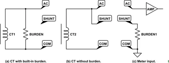
  • In the CT1 (100A:50mA) there's no burden inside, so I need an external burden to have a closed loop.
  • In the CT2 (100A:1V) it already has a burden built inside then I just need offset circuit for ADC.

I was thinking about comparator but I don't know if that is going to work. That's where I need help. I need something analogous to a switch between SW1 or SW2 depending on which CT I plugged on KRE2.

Thats what I need help, please.

If someone have a better idea for circuit topology let me know too, if I can reduce components, for instance.


1 Well, the ESP ADC isn't good enough for what we need but it's a firmware guy deal, not mine so much, and we will use the A0, A1 and A2 analog input from ADS1115 to measure current using these current transformers, because it has better resolution. I will leave A3 pin from ADS1115 open (no connect). It is for a specific application, which is just measure 3 phase current.

Dave Tweed
  • 172,781
  • 17
  • 234
  • 402
  • 2
    I don't understand your problem description, but this doesn't sound like a job for an electronic circuit at all. 3.5mm Jacks can be bought that have a simple switch inside that you can use to detect whether something is connected – for example, to unconnect the other input. – Marcus Müller May 23 '19 at 12:50
  • 1
    Note - you should never leave the secondary of a current transformer open-circuit while there's current passing through the primary. The turns ratio is high enough to produce voltages that can be dangerous, causing insulation failures (or possible shock). Bear that in mind when setting this system up. – Phil G May 23 '19 at 14:20
  • @PhilG so what do you suggest a circuit topology for it, please? – Didan Junqueira May 23 '19 at 16:47
  • @MarcusMüller 3.5mm jack wont work for me, I tried it but I have voltage when I plug p2 on second pin, however i wanna avoid manual selection by user – Didan Junqueira May 23 '19 at 16:48
  • Phil I will just one CT once a time, never both. I just need switch circuit for each one when I plug it on KRE connector. – Didan Junqueira May 23 '19 at 16:51
  • @Didan, you have no location information in your user profile but it seems as though English is not your first language. I have tried to tidy up your post for you but it is still quite a mess. Can you edit it to ask one clear question? Why are you talking about green and blue when they are not marked on your schematic? What is J7? It is very confused. – Transistor May 24 '19 at 18:35
  • 1
    I've tidied up your post again after your edit. Are the CTs supplied with the connectors on them or are you adding them? You don't need to talk about three-phase in your question. The problem is the same if you only have one phase or any number of phases so I moved that bit to the end. – Transistor May 25 '19 at 15:15
  • what else isnt unclear guys? This forum is always hold on my question, commm, im almost give up here. About CTs take a look here to understand how it works: https://learn.openenergymonitor.org/electricity-monitoring/ct-sensors/interface-with-arduino – Didan Junqueira May 26 '19 at 17:29
  • 1
    @Didan: Please read back through the comments to understand "what else isnt unclear guys". You haven't supplied the requested information. "This forum ..." This isn't a forum. It's a question and answer site so questions have to be good and clear. "... is always hold on my question, ..." That's because you don't write them clearly, and don't provide the requested information. "commm, im almost give up here." That's up to you, but why not try to respond to the comments instead of us guessing what constraints you have? – Transistor May 26 '19 at 21:05
  • 1
    "About CTs take a look here to understand how it works:" Nobody asked how CTs work. – Transistor May 26 '19 at 21:06
  • For readers here on Stack Exchange, the same question was also asked by the OP on All About Circuits forum and EEWeb forum, where there are further replies. – SamGibson May 26 '19 at 22:23

1 Answers1

1

Connection of shunt can be automated using a 3-pin connector.

schematic

simulate this circuit – Schematic created using CircuitLab

Figure 1. (a) With internal burden the CT's AC out feeds directly in. (b) When the meter's internal shunt is required a loop in the CT plug provides the connection. (c) The internals of the meter.

Wire a loop between AC and SHUNT on the connector of those that don't have one. Leave it open otherwise.

Transistor
  • 175,532
  • 13
  • 190
  • 404