1

I need adding an OVP circuit for my converter circuit.
At the 100Vdc the Brown-Out pin of my PWM controller IC will be pulled down to the ground. I did this with the circuit shown below.
But, at 80°C, the transistor is conducting too early. At 80Vdc input voltage and 80&degC, the transistor is conducting.
How can I improve this overvoltage protection circuit without temperature effects?

Thanks

enter image description here

Huisman
  • 10,694
  • 2
  • 20
  • 40
OzkulA
  • 155
  • 1
  • 8

3 Answers3

1

You need a temperature stabilized reference voltage and a comparator to do your task.

The circuit below uses the TLV431, but you could use any of the variants available. The reference voltage here is 1.2V. You should keep the current in the voltage divider about 10-20x the maximum Iref pin current or about 100uA, here I set it much higher at 500uA simply to get reasonable value resistors.

schematic

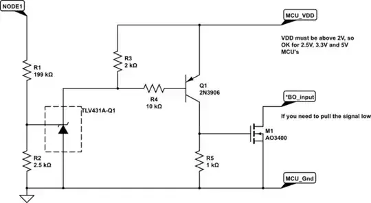
simulate this circuit – Schematic created using CircuitLab

While I calculated fixed resistors here, you might find it more appropriate to use a 200 kOhm for R1 and a pot for R2.
The threshold voltage temp variation for the input pin is about 31mV maximum over the -40 to 125degC, this should give you about 6V range on the 100V bus you are measuring. If you want to get the voltage range with temperature less than that you would need a considerably more complex circuit.

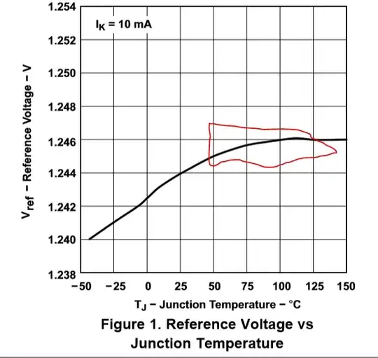
The temperature variation if the reference is shown below, and I assume you will not be using this over the whole range. As shown below, you may appreciate that you can significantly reduce the temperature variation by heating the TLV431A to 50degC in a small oven (it could even be as simple as a FET glued to the TLV431).
This would drop the temperature sensitivity to just a few mV at 100V input over the whole temperature range.

enter image description here

Jack Creasey
  • 21,729
  • 2
  • 15
  • 29
  • 1
    The OP wants the line pulled low when OVP kicks in, so shouldn't he just connect the cathode of the TLV431 directly the pin with a pull-up resistor? – DKNguyen May 27 '19 at 19:31
  • @DKNguyen NO, read the datsheet ...you can't use the TLV431 to pull down a line. The chip requires enough voltage on the cathode to power the reference …..hence it won't pull below that voltage. – Jack Creasey May 27 '19 at 22:50
  • 1
    Ah, that makes sense. I was looking at the the internal schematic under Section 8.2 but glossed over the fact that the amp has no separate power rails with which to power itself if it tries to pull the line too low. – DKNguyen May 27 '19 at 23:06
0

Your circuit uses the \$V_{BE}\$ of an NPN as its reference.

This \$V_{BE}\$ behaves the same as the voltage across a silicon diode meaning it has a temperature coefficient of around -2 mV/K. So the reference voltage goes down as temperature goes up. So indeed the NPN will switch on at a lower voltage at higher temperatures. That's totally expected behavior.

To solve this you could change the value of R1 (increase it a bit) but that would mean that the protection voltage at room temperature also increases.

If you need a constant OVP value over temperature you might need a more complex circuit.

Bimpelrekkie
  • 80,812
  • 2
  • 94
  • 185
  • Can't he just add a diode in series with R2 and adjust the divider ratio (reduce it by 0.7V to account for presence of the diode)? Should really use a circuit with a more reliable absolute voltage reference like a zener though. – DKNguyen May 27 '19 at 14:51
  • @DKNguyen NO, he can't just add a diode in series with R2 ….it won't change a thing. – Jack Creasey May 27 '19 at 14:51
  • @DKNguyen Should really use a circuit with a more reliable absolute voltage reference like a zener though This has nothing to do with reliability. This has to do with temperature stability. Zeners also have a tempco. (the 6.2 V (or 6.8 V) has the lowest though if I remember well). No one says you should use an ultra stable temperature compensated reference voltage as it depends on what you need. Only beginners go for "the best ever", more experienced designers ask: what is really needed? – Bimpelrekkie May 27 '19 at 15:58
  • @Bimpelrekkie Aren't you kind of missing the point? No one said to use an ultra-stable temperature compensated reference voltage (are zeners considered such a thing? I don't consider them such a thing). And sure Zeners have a tempco. But what doesn't? You could choose a zener so the tempco cancels out the base-emitter circuit. Alternatively, even though higher zener voltages have higher tempcos, the tempco flattens out so you could choose a higher voltage zener and take advantage of that since the tempco is a smaller fraction of the overall voltage. – DKNguyen May 27 '19 at 19:04
0

Instead of a transistor use a voltage comparator component and provide a temperature stable voltage reference. The reference voltage goes to one input and the other input of the comparator comes from the voltage divider off your battery.

Michael Karas
  • 57,328
  • 3
  • 71
  • 138