I have a level shifter that uses a transistor to control the gate of a high voltage P-channel MOSFET, like this:
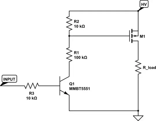
simulate this circuit – Schematic created using CircuitLab
This is designed to work at a nominal 100V HV supply, and works okay between 50 and 150V or so. The input is logic level. It works fine, except the switching time is a few microseconds.
I'd like to speed up the switching time to tens of nanoseconds if possible.
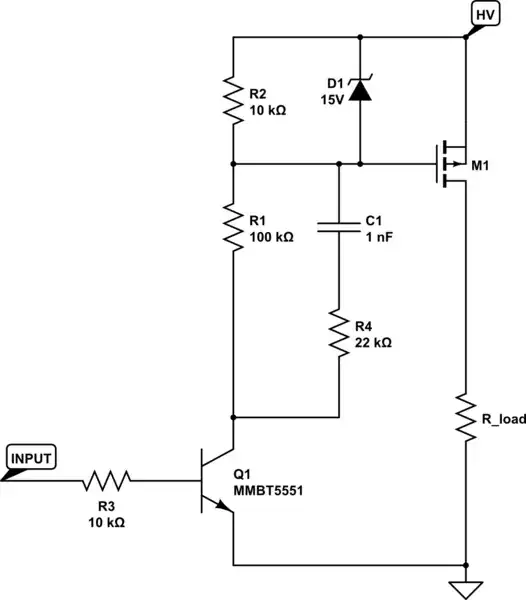
The things that make a bit tough are that the circuit is power constrained (drawing 1mA from HV through the level shifter while it's on is already kinda a lot), and also cost and space constrained (the circuit shown here fits in 15mm^2 and each component is under $0.01). I probably can't use a gate driver IC, optoisolator, or isolated gate power supply or anything along those lines. I could for example add a second BJT, some dioides or a few passives.
Is there a simple topology for speeding up switching in this type of circuit without increasing the constant power draw?