3

I've done quite a bit of searching online and can't find a solution to this (probably trivial!) problem:

I am looking to replace a resistive fuel level sensor in a car, with a solution which can be controlled digitally. A digital potentiometer is the obvious solution for this, however it doesn't appear that any exist which match the specifications:

Resistance range is 6-120 ohms. Current through the resistor during operation is up to 80mA.

The wiper resistance of most digital potentiometers is much higher than the 6 ohm minimum requirement. It seems that 80mA is also too much for most options. I have considered linking 4 or more digital potentiometers in parallel, but I'm sure there is a more elegant solution. I don't want to go down the "stepper motor and potentiometer" route unless I have to.

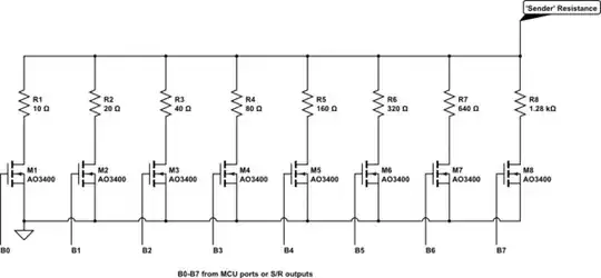
One thing I considered would be a resistor array, switched using transistors. These could be driven from a shift register, allowing suitable resolution without using too much IO on a microcontroller. After all, this is a fuel gauge, it only really needs 16 levels to be functional.

I imagine that having 7 transistors, each switching a resistor, with values of 1,2,4,8,16,32,64 ohms (or similar), it would be possible to create such a circuit. The issue is how these transistors will react when combinations of them are switched. I can't quite get my head around how to design such a circuit.

Does anyone here have experience with such a circuit? Is there a "cleaner" alternative?

Thanks for your time!

In the image below, L1 and L2 are the motor windings, R5 and R6 are fixed resistors, L7 is the potentiometer to replace.

Gauge schematic. R7 to reproduce

I guess I should add that this "digital resistor" is driving a fuel gauge directly. The gauge is a pair of motor windings, it appears that one receives a constant voltage, and the other is varied using the potentiometer as one side of a potential divider. These two coils each want to move the fuel needle in opposite directions, they seem to "fight" each other, and the whole affair ends up rotating to a position determined by the strength of the adjustable winding.

xp677
  • 33
  • 4
  • 3
    If you know whether the existing circuit that reads the resistive sensor is a constant voltage or constant current type, you could just make a current or voltage source. – The Photon Sep 02 '19 at 16:00
  • 16 levels can be achieved with 4 transistors and scaled resistors. – Peter Smith Sep 02 '19 at 16:04
  • Would a circuit such as this be functional? https://i.imgur.com/Ux0D9Zg.png – xp677 Sep 02 '19 at 16:15
  • How is the potentiometer (sensor) wired? Do you know what properties of the resulting signal the gauge is using? Is it for example voltage-based with the sensor working as a voltage divider? Or is it maybe current-based? I ask because it might be simpler to replicated the desired signal directly instead of trying to mimic one part of a voltage divider. I ask partly because of your numbers; 80mA at up to 120Ω is potentially up to 10W; I find it unlikely that much power is dissipated in your current fuel level sensor. – marcelm Sep 02 '19 at 16:16
  • I'll add some photos of the unit and the equivalent circuit that I think I've correctly reverse engineered. I commented on the answer below that the gauge is two motor windings which each aim to move the needle in different directions, the strength of the adjustable winding determines the final position. There are some fairly large fixed resistors in this unit, and the whole thing gets rather hot while in normal operation! https://i.imgur.com/anLIfJK.png – xp677 Sep 02 '19 at 16:24
  • I've had a look at currents through a potentiometer, it's around 80mA at 6R, and around 30mA at 120R. I only had a 10k pot to hand and couldn't hit 120R exactly. The 80mA was a worst-case, and I mentioned it as I see that most digital potentiometers cannot handle this current. – xp677 Sep 02 '19 at 16:36
  • I've read your question twice (and a bit) but can't figure out how or why you want replace a fuel level sensor with a digital pot. My answer to How can I make 20-200 ohm variable resistor look like a 20-240 ohm resistor? may be relevant. – Transistor Sep 02 '19 at 17:51
  • This is for an electric car conversion. – xp677 Sep 02 '19 at 20:54
  • 1
    That should be explained in the question then. – Transistor Sep 03 '19 at 06:20

2 Answers2

2

It took a while to get over the confusion you caused calling a meter a motor.
With the type of meter you have (it's a differential current meter), the two coils are used to maintain accuracy when the supply voltage varies. In your vehicle the voltage may vary from 10V or less cranking through to above 14V when charging.

Note that your particular type of meter is NOT driven by a constant current, so any answer that pushed toward that as a solution is wrong. The current through your meter varies both with supply voltage AND the 'sender' resistance value.

Your idea of using multiple resistors to create a replacement for the 'sender' is not a bad one. However you will need more bits than you imagine.

I assume that instead of a resistive sender you are going to use an MCU with some appropriate sensor to measure the fuel level ….you just want to use this conventional style meter to display the results from your MCU.

You should use FETs to turn on the individual resistor values to get the appropriate resistance value you need.

A circuit such as this may suit your application:

schematic

simulate this circuit – Schematic created using CircuitLab

Note here that I show AO3400 FETs with very small RDS(on) even when driven by a 3.3V MCU.

Even with 8 bits from the MCU or S/R the resolution around 120 Ohms is only 3 bits, but it's very easy to implement.

Jack Creasey
  • 21,729
  • 2
  • 15
  • 29
  • The OP added information about the fuel gauge mechanism after I had written my first answer, but I have updated my answer to suggest how a constant resistance could be achieved rather than a constant current. – Elliot Alderson Sep 03 '19 at 12:09
  • @ElliotAlderson Your suggested circuit is not going to provide a constant resistance, and even though the current ranges in the meter are going to be linear, it will be difficult to calibrate. – Jack Creasey Sep 03 '19 at 15:12
  • Fair enough. For the kind of meter the OP has you really need an adjustable resistance. – Elliot Alderson Sep 03 '19 at 15:20
  • This is great, many thanks. Is it possible to turn on multiple FETs at once to create combinations of resistors, or would I require one FET for each desired gauge position? – xp677 Sep 06 '19 at 23:26
  • @xp677 Yes that's exactly how you'd operate it, turn on a combination of FETs to get the gauge reading your desire. – Jack Creasey Sep 07 '19 at 03:37
0

Add a fixed resistance in parallel to give you the range you need.

Coconha
  • 75
  • 3