I have a power P-channel MOSFET that can produce a max of -34 A and whose datasheet does not include parameters W or L. How can I model this PMOS without W or L if I only have \$R_{DS_{on}} \$ and \$Q_g \$?


I have a power P-channel MOSFET that can produce a max of -34 A and whose datasheet does not include parameters W or L. How can I model this PMOS without W or L if I only have \$R_{DS_{on}} \$ and \$Q_g \$?
To model the P-MOS transistor in LTspice you do not need to know the \$W\$ and \$L\$.
The simples model used the \$K\$ factor and \$V_{TH}\$.
The drain currency is equal to:
$$I_D = \frac{K}{2}(V_{GS} - V_{TH})^2$$
And using the datascheetplot, we can also find \$V_{TH}\$ using this equation:
$$V_{TH} = \frac {V_{GS1} \sqrt{I_{D2}} -V_{GS2} \sqrt{I_{D1}}}{\sqrt{I_{D2}} - \sqrt{I_{D1}}} $$
And \$K\$ factor:
$$K=\left ( \frac{\sqrt{2I_{D1}}-\sqrt{2I_{D2}}}{V_{GS1} - V_{GS2}} \right )^2$$
For example, if we used the datasheet http://www.irf.com/product-info/datasheets/data/irf9z24n.pdf
We can use this plot:

And find that:
\$I_{D1} = 2A\$ and \$ V_{GS1} = 4.8V\$
\$I_{D2} = 4A\$ and \$ V_{GS2} = 5.5V\$
We have \$V_TH = -3.11V\$ and \$K = 1.4 \$
And finally, in LTSpice we can use this statement:
.model p1 PMOS (LEVEL=2 KP=1.4 VTO=-3.11)

But most of the time we can find a spice model of a MOSFET on google.
P-channel MOSFET that can produce a max of -34 A
MOSFETs don't produce current, this PMOS has a maximum rating of \$I_D\$ = -34 A.
In principle you can change the generic PMOS model parameters such that it will model a behavior that is somewhat to that PMOS. But it will be a hell of a job even if you know what you're doing. I would not even consider doing that.
Instead I would make a model based on a voltage controlled switch (like a relay), at a resistor of value \$R_{DS,on}\$ in series with the switch.
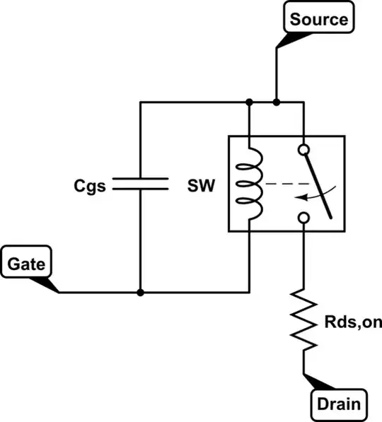
simulate this circuit – Schematic created using CircuitLab
Make the relay switch on when Vgs > Vt + 0.5 V for example. Since it's an ideal model we can make the coil resistance as high as we like, for example 10 Mohm.
Optionally add a gate-source capacitor \$C_{GS}\$ to model the input capacitance. I'm ignoring the Gate-Drain capacitance which is important when you want to do fast switching.