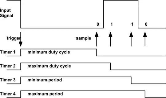
I need to design "PWM Checker" or filter - that will check that the input signal is at specific frequency (let's say 1 kHz) and specific duty cycle (let's say 33%) and the design has to use 555 chip (or 556) if the signal matches then it will pass it onwards.
The tolerance is +- 5%. I was trying to think of a solution using one 555 to measure the Ton time and another one to measure the Toff time. Each 555 circuit has two RC branches with different charge time that are feeding from the input signal (or input signal inverse for the Toff) - one connected to trigger and calculated to charge to VCC/3 after time-5% and the other branch is calculated to reach 2/3 VCC after time+5%. This is where I got stuck - how to pass the signal if both time constraints are met, or how do I make sense of the result of the two 555s?
By the way this is my solution, it doesn't have to be the only / best solution.