0

I'm currently working on an Arduino (Mega2560 based) from Industrial Shields. Model is 21+.

I use the Serial1 output (TTL 5V) to communicate with a sensor (LP8 CO2) who have CMOS 2,5V serial interface.

I've installed a divider bridge on the TX (Arduino) line to adjust the level received by the sensor. I checked the TX of the sensor, but all I see is a flat line. When I let the TX float, here is a picture of what I see:

Scope capture

I tried to pullup the signal to 3.3V with a 100k resistor but the signal just stay at 3.3V.

I would like to know what are the possible reasons of this behavior, what have I missed.

Here is the example schematic:

schematic

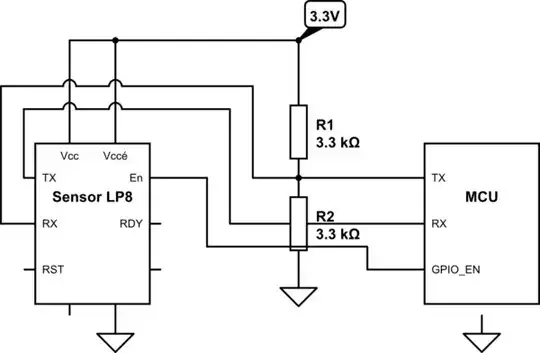
RST is internally pulled-up.

Null
  • 7,603
  • 17
  • 36
  • 48
Prof_Sims
  • 110
  • 7
  • 2
    The possible reasons would be bad hardware or firmware. Not much else can be told from the info you have provided. If you want more help, post your schematic. – Eugene Sh. Aug 20 '21 at 15:48
  • 3
    For all that picture is worth, it shows a data line having about 0.7V voltage, with TXD data superimposed on it. I wonder if some chip is missing a supply voltage. Post schematics and more info. – Justme Aug 20 '21 at 17:09
  • @prof_sims You can also edit the question and use the circuit tool to draw an example schematic – Voltage Spike Aug 20 '21 at 21:04

1 Answers1

3

You have connected the voltage divider incorrectly. The top end of the divider should be connected to the 5V TX line, not to the 3.3V power supply. The point where the two resistors connected should be connected to the 2.5V RX but not to the 5V TX.

By connecting the voltage divider according to your schematic it is possible that you have damaged the sensor.

Elliot Alderson
  • 31,521
  • 5
  • 30
  • 67
  • Thanks Elliot. I was very uncaring with this divider bridge method. The sensor work properly now. His TX line give me proper results. – Prof_Sims Aug 22 '21 at 20:17