0

here is my circuit,

schematic

simulate this circuit – Schematic created using CircuitLab

The components try to restart but no results.

Vcc output in yellow. enter image description here

I don't find in internet how to calculate Caux and Raux for starting correctly, event when I draw more current from the output.

SMPS: https://www.farnell.com/datasheets/2200510.pdf

PWM: https://www.ti.com/general/docs/suppproductinfo.tsp?distId=26&gotoUrl=http%3A%2F%2Fwww.ti.com%2Flit%2Fgpn%2Fuc3845

kodi
  • 75
  • 6
  • Seems you have a mismatch in windings orientation. The secondary winding orientation is valid for forward converter. Also, the auxiliary voltage is usually taken during transistor off-period. However, during on-period is also possible. Regarding Caux, try measure Caux ripple/voltage at worst condition - duty, different secondary loading(esp. if you are taking Vaux from flyback period). Raux is too waisted. –  Nov 16 '21 at 22:05
  • sorry, I didn't represent my circuit correctly for the secondary – kodi Nov 17 '21 at 09:48

2 Answers2

3

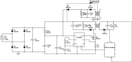
The two capacitors serve different purposes. \$C_{start}\$ is there to supply the controller at power on until the auxiliary winding takes over while \$C_{aux}\$ keeps the \$V_{cc}\$ alive in various input/output conditions.

I have detailed the calculations of these caps in my book on SPICE simulations. Below is a typical graph detailing the start-up sequence when the power is applied:

enter image description here

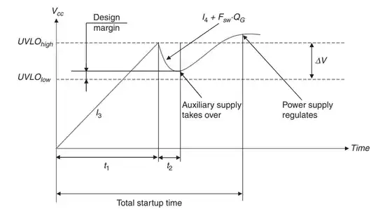
The capacitor value depends on time \$t_2\$: when the voltage across \$C_{start}\$ reaches the controller start-up level, the IC start delivering driving pulses to the MOSFET and absorbs a few mA. As the start-up resistor cannot deliver this current (you want to limit its power dissipation in an ac-dc converter), then the cap. is alone to feed the controller. As a result, it discharges towards UVLO. However, during this time \$V_{out}\$ builds up and so does \$V_{aux}\$ as windings are coupled. If \$C_{start}\$ is large enough, the auxiliary \$V_{cc}\$ will take over and self-supplies the IC before the voltage across \$C_{start}\$ touches the IC under-voltage lockout (7-8 V). In case \$C_{start}\$ is too small, the \$V_{cc}\$ touches the UVLO and a so-called hiccup takes place where the power converter auto-restarts. As \$V_{out}\$ has already built up from the previous attempt, it may start ok this time. Obviously, this is not the right way and \$C_{start}\$ must be sized so that enough headroom always exists, ensuring a single-shot start-up sequence in worst case (highest load current, lowest temperature etc.).

\$C_{aux}\$ is isolated from \$C_{start}\$ to implement a so-called split supply configuration. Even if \$C_{aux}\$ is large, it won't hamper start-up time because of the second diode going to \$V_{cc}\$. To determine \$C_{aux}\$, you need to check the \$V_{cc}\$ is always kept sufficiently high above UVLO in light- or no-load conditions (especially if the controller implements skip cycle or deep frequency foldback). You can start with a 4.7-10-µF capacitor and see how it goes. You however certainly don't want to load this cap. with a low-value resistance as shown in the sketch. Most of high-volume converters don't even have a split-supply configuration making \$C_{start}\$ and \$C_{aux}\$ the same capacitor.

Verbal Kint
  • 21,968
  • 1
  • 18
  • 55
0

Your Caux might be to small especially at light loads where Ton is short and the PWM frequency is low.

Try 4.7 to 10 uF (50 V ratings)

Take a look here. NXP uses 4.7 uF for example:

https://www.nxp.com/docs/en/user-guide/UM10506.pdf

The inductance of 6.8 uH helps filtering the square wave signal popping out of the auxiliary winding. I don't use it in my designs though.


I've never seen my life Raux in the auxiliary windings of Flyback power supplies.

Raux might be the source of the problem because it discharges quickly Caux.

Enrico Migliore
  • 4,679
  • 1
  • 9
  • 12
  • Ok I will try without Raux, however do you know a way to calculate exacly Caux and Cstart or we take values that we know it works ? Thank you – kodi Nov 16 '21 at 20:57
  • It's not that easy because some PWM controllers enter in hip-cup mode at light loads. Caux = 10 uF e no Raux should be more than enough. if you have a prototype, just disconnect the load and see if it works. All PWM controller starts thanks to an ohmic path that connects the mains or Vin directly to the VCC of the controller and not because the presence of Caux. Caux is important once the PWM controller has started and once the PWM controller has automatically disconnected, through an internal MOSFET, itself from the mains or Vin. – Enrico Migliore Nov 17 '21 at 05:11
  • Thank you, it works, put a cap of 10uF – kodi Nov 17 '21 at 13:25
  • Good to know, thanks. – Enrico Migliore Nov 17 '21 at 13:38