2

I have strange shape when I'm measuring Rsense voltage, before that circuit, I have already made a flyback conerter with this SMPS transformer https://docs.rs-online.com/696a/0900766b80107114.pdf and it works however when I make the same circuit with this SMPS https://www.farnell.com/datasheets/2706567.pdf, that doesn't works.

schematic

simulate this circuit – Schematic created using CircuitLab

Here is my shapes. enter image description here

enter image description here

In blue this is transistor shape and in yellow Vsense. PWM : https://www.mouser.fr/datasheet/2/308/1/UC3844B_D-2320086.pdf

The second picture is pin out of the pwm and Vds In blue this is transistor shape and in yellow Vout of pwm enter image description here

My circuit, sorry it's not clean enter image description here Anyone know why this signal form occurs

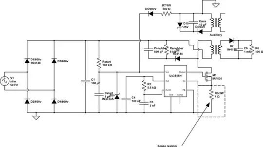
This Rsense resistor: https://docs.rs-online.com/40d8/0900766b801b8af1.pdf enter image description here

NMOS:https://www.infineon.com/dgdl/Infineon-IPP80R1K2P7-DS-v02_01-EN.pdf?fileId=5546d4625c167129015c200b9d5d467c

kodi
  • 75
  • 6
  • Looks like ringing...kind of. – DKNguyen Jan 22 '22 at 20:07
  • So you think my snubber values are wrongs, yet I hear any noise. – kodi Jan 22 '22 at 20:10
  • These are parasitic oscillations coupling onto your MOSFET gate. I've had this exact problem in a high-current flyback recently. What type of resistor did you use for R3? Could you show a picture of the resistor? – Jonathan S. Jan 22 '22 at 20:12
  • Thanks, I have posted my picture and the datasheet in the question. – kodi Jan 22 '22 at 20:22
  • Please show how you are probing. – winny Jan 22 '22 at 22:11
  • What do you mean ? I have a tektronix probe, I put the small cable at the bottom of the Rsense = R3, and the large clamp under R3 for Vds I do the same exept that the large clamp on the drain, and the small clamp at the bottom of the Rsense, so I don't probe Vds but Vd_ground. I hope my description was clear – kodi Jan 22 '22 at 22:56
  • I have a Tektronix probe as well - which one is it? Your schematic has errors. – Kartman Jan 22 '22 at 23:24
  • I have the one with bandwidth= 50MHz, Can you tell me the errors in my shematic please, thanks – kodi Jan 23 '22 at 13:54
  • Please show with a photo. Incorrect probing of current sense with strange waveforms are very common here. – winny Jan 26 '22 at 10:27
  • Thanks, I just post it, sorry if it's not very clear – kodi Jan 26 '22 at 10:37
  • Ok, your problems are much greater than expected. You can’t design and expect any switch mode converter to work in deadbug layout without a PCB and ground planes. Once you have a real PCB, you need a chip resistor and not a wirewound one, and that loop formed by your probe ground lead needs to go. – winny Jan 26 '22 at 10:49
  • Why it worked before with another flyback ? I can test it on this https://www.electronicaembajadores.com/fr/Productos/Detalle/CN21SP1/circuits-imprimes/bakelite-stripboard/plaque-dinchesessai-epoxy-type-breadboard-prt-12070 what do you think ? – kodi Jan 26 '22 at 11:05

2 Answers2

4

The resistor you chose for R3 doesn't just act as a resistor, it's also a very good inductor. As the datasheet says, this resistor is constructed by cutting a helical groove into a metal film... This creates a coil of resistive wire that has a high inductance in addition to its desired resistance.

The leads of your resistor are also suspiciously long, which adds even more inductance. You have to keep all connections as short as possible in a high-frequency switchmode converter like this.

Instead of a source resistor, your MOSFET now has a source inductor, so it's no wonder that it oscillates like crazy. You'll have to replace R3 with a low-inductance type, i.e. a high power SMD film resistor. Additionally, it might be helpful to place a small capacitor (~10nF or so) in parallel to the current sense resistor to suppress the effect of any remaining inductance. The capacitor should also be a SMD type ideally. A small resistor in series with the FET's gate might also be a good idea, i.e. 4.7 Ohms.

Jonathan S.
  • 18,288
  • 34
  • 56
  • 1
    If you're set on using a through-hole resistor, have the leads as short as possible and use a low-inductance type like carbon composition (note that this is NOT the same as carbon film), ceramic composition, or non-inductive wirewound (note that a wirewound resistor that is not specifically a non-inductive type will have far more inductance than this one!). Thick film SMD resistors like those Jonathan suggests above are also a good choice (and cheaper) if you're comfortable using SMD parts. – Hearth Jan 22 '22 at 20:53
  • Thanks, I orderI thes resistors and I post my new curves – kodi Jan 22 '22 at 22:22
  • Is this resistor low inducance ? https://fr.rs-online.com/web/p/resistances-traversantes/1372770 – kodi Jan 22 '22 at 22:49
  • @kodi No, that one is no better than your current one. Ohmite WND1R0FET would be a suitable one, for example (Digi-Key has it in stock). It has to be specifically marked as a "low inductance" type in the datasheet. If you don't mind SMD parts, TE Connectivity has the 35221R0JT, which is really large and easily hand-solderable (and a lot cheaper). – Jonathan S. Jan 22 '22 at 22:56
  • Thank you very much, I will take Ohmite WND1R0FET , sorry this is through-hole circuit. – kodi Jan 22 '22 at 22:59
  • Sorry but I just have received components but it didn't works. I just have edit my question with new pictures, thanks. – kodi Jan 26 '22 at 10:24
  • Those wires are all just way too long (and also way too thin). You still have tons of parasitic inductance that makes your FET oscillate. Fixing the inductance of your resistor is one thing, but if the rest of the circuit is still super inductive, that alone won't help. Do you think you can build the circuit on protoboard with much, much shorter connections? https://www.pcbunlimited.com/blog/wp-content/uploads/2016/11/86853685_Subscription_S1-739x500.jpg – Jonathan S. Jan 26 '22 at 11:57
  • Thanks for answering me, I'm trying to make it on protoboard , I will come back to you soon to give you my result – kodi Jan 26 '22 at 15:08
1

As @winny and @Jonathan S. say, the parasitic signal comes from the board. Thanks enter image description here

kodi
  • 75
  • 6