To me, this looks like ringing due to inductive loading from the oscilloscope probe.
Generally, oscilloscope probes act like an RC low-pass filter:
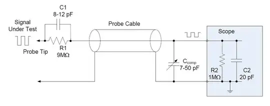
Source: https://www.allaboutcircuits.com/technical-articles/an-introduction-to-oscilloscope-probes/
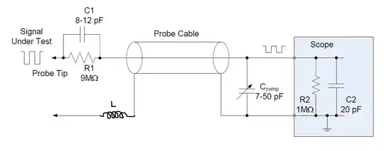
However, using a long lead for the ground connection (i.e., an alligator clip lead) introduces an inductance between the ground of the scope and the DUT:
(Excuse my paint skills)
The alligator lead in question :

This unwanted inductance alongside the capacitance of the scope and the compensating capacitance of the probe will act as an LC filter that has a resonant frequency of:
\$ f_{osc} = \frac{1}{2\pi\sqrt{LC}} \$
If your signal's rise time is faster than \$ f_{osc} \$ or rather its equivalent period, you will see oscillations after each transition. You can see that the amplitude of the ringing (in your case) is much greater on a falling edge than on a rising edge. Since the latter is much slower than the former. (I'm basing this remark on the line breaks on the falling edges is 1 break while on the rising edge it's 4 breaks).
Solution
To compensate this problem, you can use the compensation capacitor of the probe to decrease \$ C_{Comp} \$ and thus increase \$ f_{osc} \$. To do that, refer to your oscilloscope manual. But generally, it's a common procedure across all vendors. For example : Compensating the Probes
Or use a better ground connection: this answer discusses that
Te next part is not part of the answer to your question, but I thought it's nice to know.
On a different note: Using the inductive loading to your advantage
You can use this inductance introduced by the ground lead to make an antenna for picking up interferences from other devices/boards.


