This has little to to with frequency, and except for the input capacitors, the basic function of the circuit is all to do with instantaneous currents and voltages at any time, whether they be AC (changing) or DC (steady).
The potential of the upper power supply rail, labelled \$V_{CC}\$, is positive, say +12V. It must stay there, unchanging, for as long as this circuit is operating. It's not changing (at least not significantly), and has no "frequency". It's DC.
There's some ambiguity about the potential of the lower supply "rail". It doesn't have a ground symbol or a name, some I'm going to call it \$V_{EE}\$, and assume it's very negative, at -12V. Again, for this circuit to work it must remain at (or near) some fixed negative potential, like -12V DC, and contain as little AC component (fluctuations) as possible.
The "load" \$R_L\$ here is connected to ground on one (right) side, which tells you the potential at that node: 0V. The left end of \$R_L\$ has a potential which we are trying to control with the two transistors \$TR_1\$ and \$TR_2\$. The goal is to be able to precisely set the voltage across \$R_L\$, the potential difference between its two ends, by holding one end fixed at 0V and varying the potential of the other end above and below that.
There are only two ways that current can flow through that load, to the left through it, or to the right. The following diagram shows these two conditions:
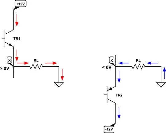
simulate this circuit – Schematic created using CircuitLab
If we intend current to flow to the right through \$R_L\$, shown in red above, by Ohm's law this requires the potential at node X to be greater than zero. Since current always flows from higher potential to lower, we must raise the potential \$V_X\$ at node X above 0V, by making \$TR_1\$ conduct, and switching \$TR_2\$ completely off, effectively removing it from the circuit. Then current is able to flow from the +12V supply down to ground via \$TR_1\$ and \$R_L\$. In this condition, we are "pushing" current into \$R_L\$.
Conversely, to have current flow in the other direction, it is \$TR_2\$ that must conduct, while \$TR_1\$ switches off and plays no role. In this condition \$V_X < 0V\$, and current will flow from the higher potential of 0V, through the load to the lower potential of \$V_X\$, and down through \$TR_2\$ to the even lower -12V supply potential. Current is colloquially being "pulled" out of \$R_L\$.
So there are two regimes, one where we push current into the load, and one where we pull current from it, giving rise to the name "push/pull". Which regime we operate in depends entirely on the conductivity state of the two transistors.
For this principle to work, \$V_{CC}\$ must stay fixed at some positive potential, and stay there, and \$V_{EE}\$ must have some fixed negative potential and stay there. This has nothing to do with frequency, and is dependent only on the transistors' states, which depends on the conditions at their bases at any given time. For instance, if we switch \$TR_2\$ permanently off, and make \$TR_1\$ perfectly conductive, then \$V_X\$ will be close to +12V, and stay there for as long as this condition persists.
The only AC (varying) potentials in this circuit are the input (which sets the conditions at the transistor bases) and the output (node X), which we aim to control. The power supplies remain steady DC potentials.
This circuit produces an output \$V_X\$ which is close to the input potential, and therefore there's no "voltage gain" to speak of. However, the current being delivered to/drawn from the load is sourced/sunk by the power supplies, and not the input signal source. As long as the power supplies are able to source/sink the required current, and the transistors can handle it, then output power is unconstrained, and all energy that arrives at the load comes from the power supplies, and not the input signal source.
The source of input signal is required to provide comparatively little current, enough to operate the biasing resistors and bases of the transistors. In this sense, while don't have any voltage gain, we do have significant power gain.
In other words, you now have the ability to control a very power-hungry load, using a signal from a source which is unable to provide the necessary power.
If I understood you correctly, you are confused about why we might need an AC voltage at all at the output. Well, \$R_L\$ could be a loudspeaker, whose diaphragm we wish to vibrate. We use current direction and amount to control the diaphragm's position, and this circuit is able to control those conditions. If \$R_L\$ were a motor, whose torque and direction of spin depends on the amount and direction of current through it, we can control that now.
It's easy to see how a loudspeaker load might require a control input signal that rises and falls above and below zero very rapidly, at audio frequencies, which is obviously "AC", but for the motor scenario we might only be changing current direction once every minute or so, to reverse the motor. Whatever the frequency of input and output signals, however often, rapidly and wildly they fluctuate, a changing signal is still, technically speaking, "AC".
The power supplies used for this circuit, though, are strictly DC.
