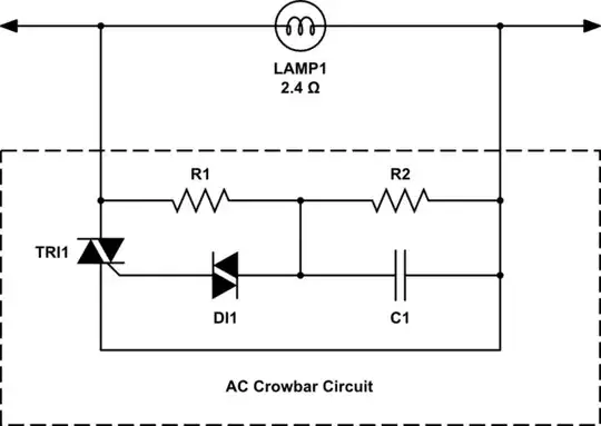
I'm developing a circuit project to bypass the current of several lamps in series in case one of them burns out.

Initially, my idea was to put a resistor in parallel with the bulb, so that when the bulb burned out, the current would pass through this resistor. The problem is that my current in the bulb can't change, i.e. I can't put a resistor equal to the resistance of the bulb, since then the current would be divided between bulb and resistor, I would have to put a resistor big enough so that most of the current would pass through the bulb while it was working. This means that when the bulb burns out, opening the circuit, all of the 6.6A current passes through the resistor and, because it has a high value, it generates a very high voltage.
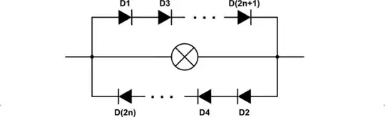
My second idea would be to put a diode in parallel with the bulbs so that when the bulbs burn out, the current would have to pass through the diodes. When I tested it with direct current, I saw that it would work, but with alternating current, I saw that it wouldn't work very well.
I would like your help to find out what else I could try. The resistance of the bulbs is approximately 2.4 ohms and the drop voltage is 15.9 Vrms.
