I am very new at this, but I am looking for a simple circuit (no microcomputer please) that will turn ON an LED for 4-5 hours, then turn OFF for 20 - 19 hours. Then it will automatically repeat this loop for as long as there is power. This will be battery-powered (3.7VDC). I would appreciate any help anyone can provide—many thanks in advance.
Asked
Active
Viewed 471 times
1
-
1Please clarify your specific problem or provide additional details to highlight exactly what you need. As it's currently written, it's hard to tell exactly what you're asking. – Community Aug 27 '23 at 06:15
-
4Sorry if it's not what you want to hear, but the simplest way to do this is to use a microcontroller. – The Photon Aug 27 '23 at 06:18
-
3It seems you want a 24hour timer that turns on a LED for between 4 to 5 hours in that 24 hours. Is that correct? Do you want the turn on time to be freely adjustable between 4 to 5 hours, or can it be any fixed duration of between 4 & 5 hours? How accurate does the 24 hour repeating function have to be, can it lose, say, 10 minutes of accuracy per day, or 1minute, or does it have to be accurate to within a second? – Fabio Barone Aug 27 '23 at 06:20
-
4Buy a ready made timer module which has a microcontroller, but does not mention it has a microcontroller, so you don't know that it has a microcontroller even if it does. – Justme Aug 27 '23 at 06:27
-
I would investigate this low frequency oscillator, LTC6995-1/LTC6995-2. https://www.analog.com/media/en/technical-documentation/data-sheets/LTC6995-6695-1-6695-2.pdf This output would need to go to some type of 4000 series CMOS counter. Read Fabio's comment carefully, you need specify your requirements more completely. – Mattman944 Aug 27 '23 at 08:49
-
Thank you all. Fabio. You are very close to what I'm looking for. Answering your questions, yes, within 24 hours, I need the LED to turn on for 4 to 5 hours. Fixing the time to 4 hours will be fine, and it doesn't need to be that accurate. A few minutes discrepancy is good. Looking forward to hearing from you! – José Briceño Aug 27 '23 at 11:18
2 Answers
2
As others have mentioned, the best and simplest solution would use a microcontroller. There are many microcontrollers, like the Arduino, that are extremely easy for a hobbyist to program.
But, just for fun, could we do it without a microcontroller, or any digital logic at all?
Sure.
For a starting point, we could use an opamp-based relaxation oscillator (https://en.wikipedia.org/wiki/Multivibrator#Astable_multivibrator_using_an_op-amp)
From the derivation in that article, the length of either phase of the oscillator is \$T=RC \ln[\frac{1+\beta}{1-\beta}]\$
In this topology, the positive and negative phase of the oscillator have the same length, but we can fix that: just use a MOSFET to change either the feedback resistance or the load capacitance based on which phase we are in.
For example, if we call the phase in which the voltage at the negative terminal is increasing the "charge" phase and the other the "discharge" phase, and we have a different feedback resistance in each phase, then:
\$T_{charge}=R_{charge}C \ln[\frac{1+\beta}{1-\beta}]\$ and \$T_{discharge}=R_{discharge}C \ln[\frac{1+\beta}{1-\beta}]\$
Here's an example circuit with \$C=400nF\$, \$R_{charge}=5k\Omega\$ and \$R_{discharge}=10k\Omega\$.

As we expect, the positive and negative phases of the output are ~ 2.2 ms and 4.4 ms respectively.
To make your timer run for hours, the passives should be a few orders of magnitude larger. With \$R_{charge}=1 M\Omega\$, \$C=10mF\$, and \$\beta=0.8\$, you can have a charging time of ~ 6 hours.
At this point, you have some other problems... you need to check that the MOSFET's gate is rated for the opamp's output voltage, make sure you don't have any leakage resistance on the order of a megaohm, and take extra care that your 10 mF supercapacitor doesn't explode in your face.
But I'm hoping you don't build this at all, because as mentioned, an Arduino can do it better. :)
Adam Q
- 607
- 3
- 9
2
This is how I would have done this in 1976. You can only expect about 1% accuracy with a 555 timer circuit. So, if 14 minutes per day accuracy isn't good enough, you may need to use a crystal oscillator.
You can calculate R2, R3, & C1 from the datasheet. C1 must be a stable cap, a mylar or something similar.
U1 and U2 could possibly be combined into the chip that I referenced in the comments.
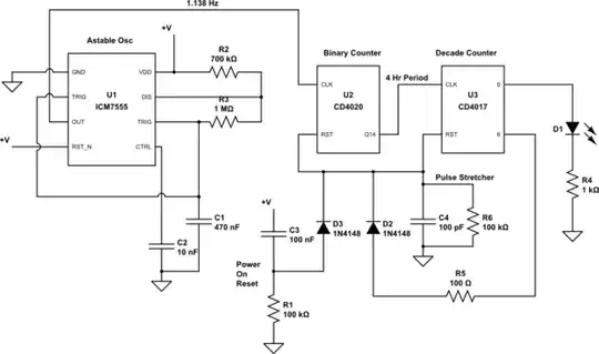
simulate this circuit – Schematic created using CircuitLab
Edit: R2 should be a fixed resistor in series with a pot. You don't want to use a 1M pot, it will be too hard to make fine adjustments.
Edit2: I built the circuit, it works fine.
Calibrating is tricky. Ideally, you want to use a quality lab frequency counter with a period measuring function. My scope will measure period, but with less accuracy. Without an instrument, you need to get creative. Temporarily change the U2 output to Q1. Then measure the time to get 10 LED pulses with a stopwatch. It should be 105.5 seconds. You should be able to set the initial accuracy to a few tenths of a percent with this method.
The 7555 is slightly sensitive to power supply voltage. When I changed the voltage from 5V to 4V, the period was reduced by 0.5%.
The period will also change with temperature. How much will depend on the quality of your components. But, if your circuit will be used inside, this should not be a major factor.

Mattman944
- 15,935
- 1
- 20
- 47
-
I had a car of that vintage and inside the clock there was a 555. It was used to as a timer to trigger the motor to wind the analog, mechanical clock ever half hour or so. – D Duck Aug 29 '23 at 15:01