Debugging the code from the question
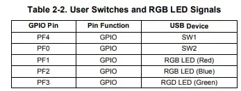
Based upon the information in the question, I assume the code is being run in a EK-TM4C123GXL. The Tiva™ C Series TM4C123G LaunchPad Evaluation Board User's Guide contains the following table which shows the connections for the LEDs and switches on the board:
I added the code from the question into a CCS 12 project for a TM4C123GH6PM so could debug by single stepping. Before stepping into the while loop the LEDs on the board are all off. The TM4C123GH6PM datasheet description of the GPIO Data (GPIODATA) register shows that the register is initialised to zero on reset.
The result of stepping through the while loop after starting the program while not pressing any button is:
Value read from GPIO_PORTF_DATA_R |
Value written to GPIO_PORTF_DATA_R |
Comment |
| 0x00000014 |
0x7FFFFFF7 |
RGB LED changes from Off to Blue+Red On (Magenta) |
| 0x00000016 |
0x7FFFFFF4 |
RGB LED changes from Blue+Red On to Blue On |
| 0x00000014 |
0x7FFFFFF5 |
RGB LED remains at Blue On |
| 0x00000014 |
0x7FFFFFF5 |
The shift register on GPIO_PORTF_DATA_R is now stable |
The SW1 button was pressed and continued stepping:
Value read from GPIO_PORTF_DATA_R |
Value written to GPIO_PORTF_DATA_R |
Comment |
| 0x00000004 |
0x7FFFFFFD |
RGB LED changes from Blue On to Green+Blue On (Cyan) |
| 0x0000000C |
0x7FFFFFF9 |
RGB LED changes from Green+Blue On to Green On |
| 0x00000008 |
0x7FFFFFFB |
RGB LED changes from Green On to Green+Red On (Yellow) |
| 0x0000000A |
0x7FFFFFFA |
RGB LED remains at Green+Red On |
| 0x0000000A |
0x7FFFFFFA |
The shift register on GPIO_PORTF_DATA_R is now stable |
So, effectively the code is creating a shift register on some bits of the GPIO_PORTF_DATA_R register, where the output bits for the LEDs can be read back on the next iteration around the while loop.
Consider changing from Direct Register Modification (DRM) only programming to using TivaWare
The [FAQ] FAQs for TM4C Arm Cortex-M4F Microcontrollers on the Texas Instruments forum contains the following:
4) Avoid use of Direct Register Modification (DRM) only programming, and instead use TivaWare.
One of the primary purposes of TivaWare has been to remove the need for individual users to learn the ins and outs of DRM programming. For this reason, we will not be able to offer support for any questions that only pertain to DRM programming.
Where the code from the question is using DRM programming. If the program was re-written to use TivaWare functions it could be clearer. E.g. the GPIOPinWrite function takes the ui8Pins argument which is a bit-mask of which GPIO port output bit(s) to update. By changing the code to use TivaWare GPIOPinWrite could be used to only update the PF1 state for the RGB LED (Red) on the board.
If required, could modify this answer to add an example of how the DRM code in the question could be converted to TivaWare.

value. (You may need to disable optimizations to see the results of each line individually.) Double check the schematic to ensure the red LED is on the pin you expect. – kkrambo Oct 21 '23 at 09:33Next, we invert this value ~0b xxx0 xxxx so we get this 0b xxx1 xxxx
Now we shifted to the right by one 0b xxxx 1xxx And we send it back to GPIO_PORTF_DATA_R register. This works because we have a switch on pin PF4 and the LED on pin PF3.
– G36 Oct 21 '23 at 13:08