I was studying NOT gates, and I can't understand why current stops passing in LED when the switch is on. If the potential difference between top and bottom is 5V, should current always flow between the available paths between the top and bottom?

I was studying NOT gates, and I can't understand why current stops passing in LED when the switch is on. If the potential difference between top and bottom is 5V, should current always flow between the available paths between the top and bottom?
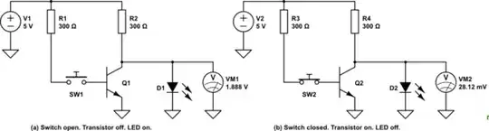
The issue is that both the transistor and the LED are nonlinear devices — i.e., the voltage across them and the current through them are not related by a simple constant.
In particular, the LED current drops essentially to zero when the voltage across it drops below its \$V_f\$ or "forward voltage" rating. For most LEDs, this is well over a volt.
In contrast, when the transistor is switched on (saturated), the voltage drop across the collector and emitter is at most a few tenths of a volt. Therefore, all of the current from the resistor flows through the transistor and not the LED.
When the transistor turns on, most of the voltage is dropped across the resistor, leaving very little for the LED. An incredibly tiny current will flow through the LED, probably not enough to measure with an ordinary multimeter* and certainly not enough to create visible light.
Here is a simulation with an OSRAM white LED model and common NPN BJT, with some resistor values that would typically be used in a real circuit.

As you can see, the current through the LED D1 is predicted to be only 100pA.
The LED has a very nonlinear V/I curve. If you were to think of it as a resistor, the 'resistance' when the LED is on would be 2.76V/2.2mA or about 1.25kΩ. When the LED is off it would be 0.072V/1E-10A or about 700MΩ. Which is why we don't think of it as a resistor, but instead (at the simplest) think of it as having a fixed Vf when on. If it was a 1.25kΩ resistor it would be conducting more than 50uA with the transistor on.
With the transistor 'off' (left side of R1 grounded) the current through D1 is 2.2mA and the current into the BJT collector only 3pA.
* If you did want to measure it and all you had was a multimeter with 10MΩ input resistance and a 199.9mV DC scale (typically the current scales on inexpensive multimeters are way too high for this purpose), you could set the multimeter to measure voltage, and the 100pA predicted leakage would result in a 1.0mV reading on the multimeter (so 10% resolution, not great, but better than nothing). It's important to know the input resistance of your multimeter for this to work.
simulate this circuit – Schematic created using CircuitLab