
- I think the potential difference (top) between the voltage sources is either 6V (15-9) or 15V (the bigger one wins?).
- The potential difference between the resistor and V1 is -15V.
Is this correct?
Is this correct?
It looks like you are using German notation for your voltage gradient. (English / American would have the arrows pointing to the higher potential.)
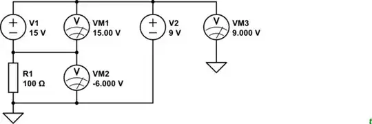
simulate this circuit – Schematic created using CircuitLab
Tip: when you use the editor's CircuitLab button and Save and Insert a PNG is generated and a link to the schematic so we can edit and copy it into our answers. No CircuitLab account. No screengrab. No grid.
From the comments:
What will happen if i remove the resistor and connect v1 directly to ground. What will be the potential on the top? Still 9 V?
If you are using ideal voltage sources with zero internal resistance you will create an impossible situation. The top rail will be +15 and +9 V simultaneously and this is not possible.
If we add some internal resistance we'll get this. (I've chosen low internal resistances like in a lead-acid battery.):
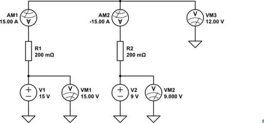
*Figure 2. If the power-supplies have internal resistance or current limiting then V1 will source 15 A and V2 will sink 15 A if the PSU can sink current. (Batteries can sink current at a specified safe rate until charged and then you have a new problem - and possibly a mess to clean up!)
Assuming ideal voltage sources (zero series impendence), you take the difference of the voltage sources. The sum of the voltage drops across all the elements in the loop have to net to zero volts (KVL). Therefore, the resistor sees -6V WRT ground.
"The potential difference between the resistor and V1 is -15V" This statement is incorrect.