I'm looking for an analog SPDT switch which will block reverse current if in open state.
The circuit operates in two modes:
- LED on (SW1 and SW2 in closed state)
- LED off (SW1 in closed, SW2 in open state)
In mode 1 both switches are closed, forcing the LED to emit light fed by the current flowing from the power rail to GND. In mode 2 SW1 is open (blocking the power rail) and the LED is used a a current source feeding the photo current into a multi-stage transimpedance amplifier. Naturally, the photo current flows in the opposite direction (from GND to the negative input of the transimpedance amplifier).
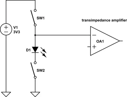
simulate this circuit – Schematic created using CircuitLab
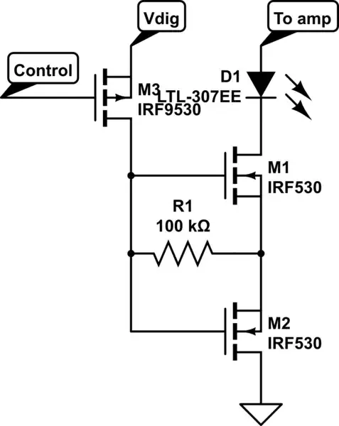
My design uses a matrix of LEDs (common cathode) to detect incoming rays of light and a microcontroller turns the switches on and off. Scanning through the sensor rows requires selecting a single row (turning on SW1 for that row) while turning off the SW1s of all other rows.
I'm currently using SN74LVC1G3157DCKR analog switches which work pretty good for mode 1, but don't work in mode 2, as reverse currents are not blocked by open switches. So I'm unable to turn off all rows but the one that should get measured and instead the photo current flows through all open SW2s.
The problem can be seen here when feeding AC current through a closed and through an open SW2.

