2

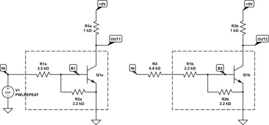
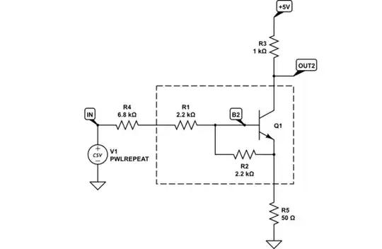
In a PCB design I decided to replace a 2 kΩ resistor plus a MMBT3904 with a dual NPN transistor with built-in resistor in a SOT-363-6 package to save space and number of components. The part is MUN5231DW1T1G (R1 = 2.2 kΩ, R2 = 2.2 kΩ).

Thd base is driven from an MCU running at 5 V.

With the original solution, [MCU <> 2 kΩ <> MMBT3904], when the I/O goes from 5 to 0 V, the collector stops sinking current after ~500 ns:

oscilloscope screenshot

With the current solution, [MCU <> MUN5231DW1T1G], when the I/O goes from 5 to 0 V, the collector stops sinking current after ~1500 ns:

oscilloscope screenshot

Parts with a higher R1 value like the MUN5232DW1T1G or the PUMH15-QX (R1 = 4.7 kΩ) made it worse.

Parts with a lower R1 value like the MUN5230DW1T1G (R1 = 1 kΩ) made it slightly better, but still more than two times slower than the original solution.

Why such a difference?
What should I be looking for in order to find a SOT-363-6 replacement that's closer to the original solution?

ocrdu
  • 9,195
  • 22
  • 32
  • 42
Luna
  • 41
  • 3

3 Answers3

5

The MUN5231 is designed as a load-switching transistor. It is optimized first and foremost to have low collector-emitter saturation voltage, speed and current gain come second.

The MMBT3904, on the other hand, is a general-purpose amplification transistor. It is designed to be fast and have high gain, but this comes at the expense of higher collector-emitter saturation voltage.

You quite simply chose the wrong transistor. If the 1500ns turn-off time is a problem, you should look for a replacement that actually specifies both the storage time and turn-off time in its datasheet.

Jonathan S.
  • 18,288
  • 34
  • 56
3

Without knowing the periphery of the circuit, and what it's driving, it's impossible to say whether the following is useful to you or not. Still, here's my tuppence.

The transistor can be biased in such a way as to never deeply saturate:

schematic

simulate this circuit – Schematic created using CircuitLab

The internal bias resistors of the MUN5231DW1T1G make it easy to control maximum base potential with a single resistor, R4, on the right. On the left, I haven't added any such resistor.

I've chosen R4 such that the resistor divider provides close to 1V at the base (if the transistor weren't there), when the input is +5V:

$$ V_{B2} = 5V \times \frac{R_2}{R_4+R_1+R_2} = 1V $$

This prevents Q1 from deeply saturating, permitting it to recover much more quickly. This is the input signal:

enter image description here

Outputs OUT1 (blue) and OUT2 (orange):

enter image description here

As you can see, Q1's recovery from saturation is much quicker.

That requires a single extra resistor, if you employ the transistor with built-in resistors, but nothing's stopping you from using a regular transistor and combining R4 and R1.

The success of this approach depends heavily on R4, and input potentials. To mitigate that dependence you could employ emitter degeneration, with R5 here:

schematic

simulate this circuit

This reduces Q1's saturation even further, at the cost of a slightly elevated low output potential:

enter image description here

Simon Fitch
  • 34,939
  • 2
  • 17
  • 105
2

Interesting data point. I've only ever used these things for slow applications. I tried simulating one that had a SPICE model and said to use a transistor with an ft of 250MHz (as opposed to no speed-related figures at all), and it was even slower (1.78us). ft is something you can search on. I extracted the transistor model from the Rohm EMH3 and used two 2.2kΩ resistors and a 1kΩ load resistor. Below is the transistor model. I did not attempt to verify the ft number.

.MODEL QDTC1 NPN (IS=20.000E-15 BF=198.80 VAF=15 IKF=.28787 ISE=20.001E-15 NE=1.6289 BR=8.4556 VAR=100 IKR=.2645 ISC=8.0686E-12 NC=2.3678 NK=.75224 RE=.2 RB=10.670 RC=1.1274 CJE=11.342E-12 MJE=.38289 CJC=4.0230E-12 MJC=.34629 TF=500.00E-12 XTF=580.91 VTF=195.13 ITF=19.351 TR=200.00E-9 XTB=1.5000)

You could go searching for similar parts with SPICE models and hope that they are accurate and will represent (and continue to represent) the parts sold (since there are no numbers on the datasheet to guarantee anything switching-speed related). With a company like Rohm they probably will, as long as they continue to make the part, with some other makers it's less sure.

Or.. if you need to save space and get on with things maybe you could use a dual MMBT3904 and a 4-resistor network.

enter image description here

enter image description here

Spehro Pefhany
  • 397,265
  • 22
  • 337
  • 893
  • I'm looking for the same type of device (with integrated resistors) since I already got some PCBs. I tried the SPICE model provided by onsemi for the MUN5231DW1T1G but it stops current flow almost immediately in simulation. – Luna Feb 16 '24 at 15:48
  • @Luna .. sad.. I guess the "hope they are accurate" in my answer was necessary. I confirmed your observation by pulling the 'qmodel' transistor model out of the MUN5233 single model. I'm not familiar enough with the more arcane parameters of the Gummel-Poon model to see immediately where the issue is. – Spehro Pefhany Feb 16 '24 at 16:17
  • .MODEL qmodel npn +IS=1.11089e-14 BF=320.82 NF=0.980954 VAF=13.7591 +IKF=0.0454909 ISE=1e-16 NE=1.17033 BR=4.34852 +NR=1.0038 VAR=99.7542 IKR=0.156455 ISC=9.81183e-14 +NC=2.87399 RB=0.1 IRB=0.2 RBM=0.1 +RE=1.81526 RC=0.001 XTB=1.73971 XTI=1 EG=1.206 +CJE=7.02461e-12 VJE=0.74856 MJE=0.331575 TF=1e-09 +XTF=1 VTF=10 ITF=0.01 CJC=4.71202e-12 +VJC=0.95 MJC=0.401177 XCJC=0.9 FC=0.5 – Spehro Pefhany Feb 16 '24 at 16:17