-3

I am looking for a working comparator circuit that doesn't include any op-amp, using any of the basic elements like capacitors, BJTs, MOSFETs, resistors, etc.

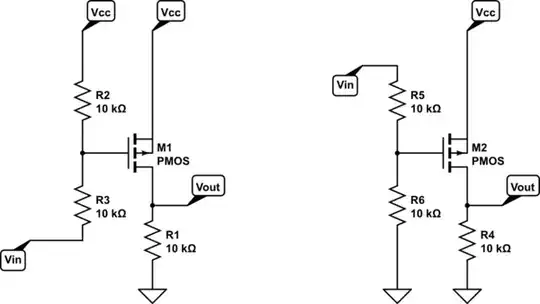
The circuit should work as an inverting op-amp, that is, if the input voltage is below the threshold voltage, it should send VCC to output, and if the input voltage is over the threshold voltage, it should send GND to output. It is somehow like a NOT gate with a comparison threshold.

Simply, I used a divider circuit, connected the divider output to the base of mmbt2222, and then tied its emitter to GND. then pulled up its collector with another resistor. Finally, the output would be the collector pin. This way I could control the threshold, but the base input current problem arises.

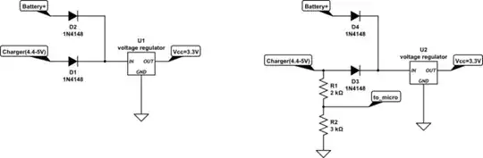
Vcc is 3.3V. input voltage would be 3.7v in one case and 1.5v in another case. This circuit would be used for USB charger detection, and its output would go to the STM32F103rbt6 GPIO. battery charge is measured with analog input, but when the charger is present, analoge voltage would become the same as VCC, like when the battery is fully charged, making it inaccessible to use it for charger presence detection

V.Ajall
  • 71
  • 4
  • 1
    Is this a homework assignment? – evildemonic Mar 27 '24 at 17:41
  • Can you ask an answerable question? Now you are just explaining what you are looking. – Justme Mar 27 '24 at 17:42
  • 1
    @evildemonic Completely an industrial circuit, used for checking if the charger is inserted or not, to reduce cost. – V.Ajall Mar 27 '24 at 17:43
  • @Justme I know an lm358 based circuit is a good answer, but I am looking for a lower-price answer. – V.Ajall Mar 27 '24 at 17:45
  • 1
    @V.Ajall LM358 is not a comparator, it's an op-amp. Op-amps don't work well as comparators, and comparators don't work well as op-amps. Can you just buy a comparator? – Justme Mar 27 '24 at 17:47
  • @Justme LM358 can be used in a simple comparator circuit with some resistors aside. Any suggestion for an analog comparator with inverting output? which has the cost lower than lm358? – V.Ajall Mar 27 '24 at 17:48
  • 3
    @V.Ajall How about, say, a comparator? It will be cheaper than making the equivalent with discretes and perform better. – MOSFET Mar 27 '24 at 17:58
  • 3
    TI has 293 comparator part numbers, starting at $0.044 each, budgetary pricing. Compared to $0.05, any discrete solution using 4 or more components is going to be more expensive due to assembly costs. – The Photon Mar 27 '24 at 18:15
  • @V.Ajall Better questions would be, why do you need this? Why are you against using comparators when they are designed for exactly what you are trying to achieve. And if you have a micro, why not use an ADC input, and do the comparison in firmware? Also, your title and body is poorly worded (op-amp != comparator). – MOSFET Mar 27 '24 at 18:39
  • @V.Ajall Can you edit the question to include which microcontroller is used, to determine the microcontroller has any peripherals which could help. – Chester Gillon Mar 27 '24 at 18:43
  • This answer regarding a solar panel + battery project might provide some ideas -- it includes a simple BJT comparator and a status output. – Dave Tweed Mar 27 '24 at 19:04
  • @DaveTweed If I meant to use this many discrete elements, I would have used a simple comparator instead. – V.Ajall Mar 28 '24 at 09:35

3 Answers3

0

I have one cheap solution, provided you don't need a precise threshold, nor a strong drive, and you can accept some "in between" state.

If you use a PMOS with a pull-down resistor, then if the input voltage is bellow Vcc-Vth (Vth beeing the (absolute value of) the threshold voltage of the PMOS), then the mosfet is conducting, and you get Vout=Vcc. Otherwise, the mosfet is blocked, and the pull-down resistor gives you a (weak) Vout=GND.

NB : in real life, when you are very near Vcc-Vth, the mosfet is partially conducting, and Vout might end somewhere between GND and Vcc : this might not be a problem if Vin change fast, or your voltage is near the threshold, or if your next step has some internal threshold. Or it can be a game killer. It depends on application.

Also note that Vth has big fabrication tolerances, so you won't get a precise threshold.

Now what if you want to compare to a value other than Vcc-Vth : simply add a voltage divider between your input and Vcc (if you want to switch above Vcc-Vth), or between input and GND (if you want to switch bellow Vcc-Vth)

schematic

simulate this circuit – Schematic created using CircuitLab (adapt the resistors as needed)

NB : if you need a clean output, you can replace the PMOS+pulldown by a not gate (with the voltage divider to set the threshold). Or use a NMOS+pull-up, followed by a home made not gate (either one NMOS + one MOS, or NMOS + pull-up, or PMOS + pulldown)

EDIT : if I understand correctly your current circuit (left side), then I suggest the circuit on the right (NB : after new comment, it seems there is only one diode, so it might not work):

schematic

simulate this circuit

Sandro
  • 7,277
  • 11
  • 37
  • This is the problem I have encountered. my VCC is supposed to be 3.3v. since my charger is USB, Vin in case of USB present would be 4.4v to 5v. when there is no USB, since I used some behind circuit, it would be 2.2v while battery is present. – V.Ajall Mar 27 '24 at 18:09
  • Do you need the signal to be inverted (ie high when on battery), or is the other way (high if on charger) also OK? The second solution is a bit easier and probably cheaper : we can use a NMOS instead of a PMOS (cheaper, more choice, and it's a little bit easier to design with Vth instead of Vcc-Vth) – Sandro Mar 27 '24 at 18:19
  • No difference, since the output will go to the microcontroller for display, and it can be interpreted in microcontroller – V.Ajall Mar 27 '24 at 18:28
  • What is your micro-controller (and it's supply voltage)? It is probably possible to just use a voltage divider on Vin (to get it bellow the supply voltage of the micro-controler), then either feed it to an analog input (if you have one), or to a digital one (in this case, you have to choose precisely the voltage divider ration q, so that q2.2V is bellow the threshold of the digital pin and q4.4V is above (and q*5V is bellow the max voltage supported) – Sandro Mar 27 '24 at 18:36
  • PS : can you please clarify the exact ranges for the 2 possibilities (the ones you put in the comments are different than the ones in the edits of your post) – Sandro Mar 27 '24 at 18:38
  • Since the battery and charger voltage fluctuate, I use analog input only for battery voltage measurement, and charger presence should be checked via an external input. – V.Ajall Mar 27 '24 at 18:40
  • VCC is 3.3v. I had used one 1n4148 diode behind my voltage devider. so input usb voltage would be between 4.4 to 5v after the diode it would range from 3.7 to 4.3. input voltage in battery case is 2.2v, and this is why I mentioned input would become 1.5v. – V.Ajall Mar 27 '24 at 18:44
  • So you have 2 diodes, one for the USB charger, and one for the battery : correct? If so, there is an even simpler solution : put a voltage divider on the battery charger BEFORE the diode to map 5V to about 3V. This way, if the charger is present, you will read high, otherwise, you will read 0V – Sandro Mar 27 '24 at 18:48
  • AHA, there is a problem, I have used a USB ESD suppressor, and it makes things difficult, (I should use it). and no I have only one diode. its behind input voltage. – V.Ajall Mar 27 '24 at 18:53
  • Can you share the schematics of your circuit (at least the relevant part with the 2 inputs)? – Sandro Mar 27 '24 at 18:55
0

Maybe you could use a PNP BJT, a couple resistors and Zener diode. Cost could be slightly less than a cheap LM358 if assembly is almost free. But there are many details left unsaid.

Spehro Pefhany
  • 397,265
  • 22
  • 337
  • 893
0

This circuit would be used for USB charger detection, and its output would go to the STM32F103rbt6 GPIO

The STM32F103RB datasheet shows some pins are 5 V tolerant.

The ST AN4879 Introduction to USB hardware and PCB guidelines using STM32 MCUs has a section on VBUS sensing detection:

The recommended resistor divider values for VBUS detection are the following:

  • For VDD in 3.0-3.6 V range: 82 kΩ (to GND), 33 kΩ (to VBUS).
  • For VDD in 1.8-2.0 V range: 68 kΩ (to GND), 82 kΩ (to VBUS).

It is recommended to implement a resistor bridge (refer to Section 2.6 for more details). It is also recommended to use an ESD protection device and to place it as close as possible to the USB connector. enter image description here

While the question doesn't mention the need to perform USB communication, perhaps VBUS from the USB charger be sensed with a resistor divider connected to a GPIO as suggested in AN4879.

Chester Gillon
  • 3,690
  • 1
  • 11
  • 15