3

I want to light 1 red LED among 3 (or no LED at all; never 2 or 3 simultaneously), using 3 output ports of a micro-controller (PIC18LFxxx or so). The catch is that I'm operating from a low and variable voltage supply Vcc_IN of 2.2V to 3.1V, and want to avoid too much variation in the LED current (I'm content with like 2mA, give or take 25%). This simple solution won't cut it:

schematic

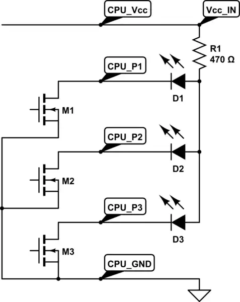
simulate this circuit – Schematic created using CircuitLab

Instead of R1, it looks like I need an ultra-low dropout 2mA current source. Also my application requires a low current consumption, especially when Vcc_IN is minimum (2.2V), for then I have barely enough current available for 2mA in the LED. What reliable, easily sourced, cheap, simple solution is there?

Clarification: A key issue is the very low voltage margin between the red LED's forward voltage @2mA (say about 1.7V) and the minimum Vcc_IN voltage (2.2V); these mere 0.5V must be enough for the dropout voltage in the Mx transistor (say about 0.2V) and the current source. Notice that if I adjusted resistor R1 experimentally to get an appropriate current at the low range of the supply voltage, the LED current would increase dramatically with power supply voltage.

I thought I had found a solution using one of the output of a MAX1916 (and reversing the polarity of the CPU output ports). The current regulator section of that IC (featuring a MosFET current mirror with x230 gain) would be quite nice for my use, unfortunately it seems that I do not have enough voltage to force the IC in ON mode.

fgrieu
  • 1,670
  • 2
  • 15
  • 24
  • Have a look at Adafruit's Neopixels -- they might address your problem. http://learn.adafruit.com/adafruit-neopixel-uberguide/ – Brad Nov 22 '13 at 23:37
  • @Brad: thanks, but their lower power supply voltage (5V nominal) is significantly higher than my 3.1V maximum, so we are facing different challenges. – fgrieu Nov 22 '13 at 23:54
  • Fgrieu, just checking, you realize your circuit above, the three leds if on at the same time, will share that 2mA between the three of them, right? – Passerby Nov 23 '13 at 01:23
  • @Passerby: I do. As stated, only one out of the three will be turned on at any time. – fgrieu Nov 23 '13 at 07:59

2 Answers2

2

You can use a boost regulator to get a constant and higher voltage (e.g. 3V3), put a resistor in series with each LED, and turn on/off each LED with a MOSFET on the low side.

apalopohapa
  • 8,459
  • 2
  • 30
  • 39
  • Op wants/needs 3 individually controllable leds. The ZXSC400 is single output. – Passerby Nov 23 '13 at 01:13
  • @Passerby Thanks, I misread, I've edited the answer to reflect this. – apalopohapa Nov 23 '13 at 01:20
  • I would need a 2.2V to 3.1V -> Vreg=3.xV boot or charge pump. Locally generating a stable voltage is a bit complex, but at least it works!. And as long as the unregulated Vcc_in is comfortably less than 4V (my case), I do not even need a discrete MOSFET on the low side (when the port is high, or high Z, its LED won't conduct). – fgrieu Nov 23 '13 at 08:37
0

This answer https://electronics.stackexchange.com/a/27470/17178 gives three options. 1) A lm317 as a current limiter, 2) a discrete 2 transistor + 2 resistor setup, or 3) a LM234, a dedicated adjustable current source.

Note, the LM317's datasheet states that the minimum load is 10mA, you could do this with a parallel resistor, or skip it, if your testing shows it to be stable enough. Since you are simply using it for leds, it's not too important. But it has a relatively high dropout (1.25V).

Another option is a relatively simple boost converter. A chargepump, inductorless boost converter like the Texas Instruments TPS60240 15mA Boost Converter would work. 4 1uf capacitors are all it needs. Or a higher current tps61097-33 (two caps, one inductor). Boost the VCC to a regulated 3.3v, then you don't have to worry about the VCC changing.

Passerby
  • 73,027
  • 7
  • 93
  • 209