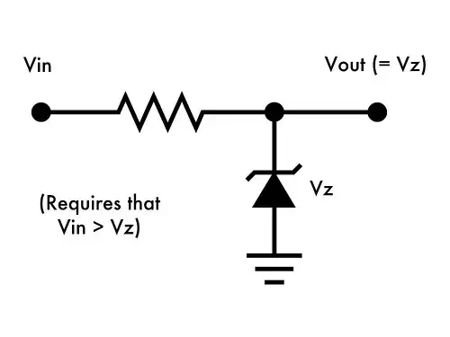
In this circuit, if:
- Vin = 9V
- Vz = 5V
I understand that Vout will be 5V. Does that have to do with Kirchhoff's Voltage Law? How does the zener diode, if it drops 5V to ground, cause Vout to also be 5V?
In this circuit, if:
I understand that Vout will be 5V. Does that have to do with Kirchhoff's Voltage Law? How does the zener diode, if it drops 5V to ground, cause Vout to also be 5V?
Does that have to do with Kirchhoff's Voltage Law?
Yes, by KVL, \$V_{out} = V_z\$.
How does the zener diode, if it drops 5V to ground, cause Vout to also be 5V?
Another way to 'see' this is the load (not shown) is in parallel with the zener diode and, as you know, and by KVL, parallel connected circuit elements have identical voltages.
The circuit with load:
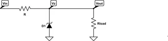
simulate this circuit – Schematic created using CircuitLab
See that the zener diode and load are parallel connected and thus, the voltage across the load and voltage across the zener diode are identical:
$$V_{out} = V_z $$
Zener diode passes a lot of current (has low resistance) if the voltage is above Vz. So, connected in a circuit like in the question:
So, the circuit reaches an equilibrium of Vout=Vz. If the voltage tries to go lower (a load is connected), the diode conducts less and the voltage rises back up to Vz. If the voltage tries to go higher (aload was disconnected) then the diode would conduct more and drop the voltage down to Vz.
Rhetorical question: What's the current through the zener?
This might help:
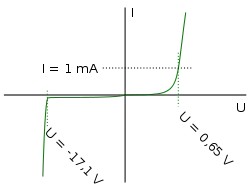
As you can see, once the voltage hits the zener voltage (-17.1V in this case), the zener starts conducting a lot of current, really fast.
Now what's the voltage across the resistor?
We know from Ohm's law that the voltage across the resistor will be \$E = IR\$. So as the zener starts conducting a lot of current, the current through the resistor will go up also, and by Ohm's law, so will the voltage across the resistor.
When the voltage across the resistor increases, the voltage across the zener must decrease (that's Kirchoff's voltage law). If it were to decrease too much, the zener would stop conducting, and then there would be no current, so the resistor voltage would fall to zero, and the zener would again see \$V_{in}\$ and conduct.
Thus an equilibrium is reached: the zener conducts just enough current to make the voltage drop across the resistor equal to \$V_{in} - V_z\$.
A zener regulator such as this has two problems. Firstly, quite a lot of current can flow in the resistor and the zener, even when no load is connected. This is inefficient.
Secondly, as the load draws more current, the zener has to conduct less current, because the current through the resistor (which determines the output voltage) is the sum of the zener current and the load current. At some point, the load draws enough current on its own such that the zener doesn't have to conduct any. If the load current is further increased, the voltage drop across the resistor will be too much, and since the zener can't source current (only sink it), \$V_{out}\$ becomes less than \$V_z\$.
Zener diode is a non-linear component. When Vin>Vz, and there is a current flowing through the zener, the voltage drop of the zener will be always Vz. The voltage drop of the current-limiting resistor will always be Vin - Vz, which in your circuit will be always 9V - 5V = 4V. The 4V voltage drop of the resistor is independent of its resistance value. The size of the resistor only determines the amount of current flowing through the zener diode.
For example, if the zener is rated 1W, then maximum current that can safely flows through the zener is 1 / 5 = 200mA. So the value of the resistor will be (9 - 5) / 0.2 = 20Ω. In case the zener used is rated 1/2W, it can safely pass through 100mA current, the value of the resistor will be (9 - 5) / 0.1 = 40Ω. Using V = IR, the voltage drop of the resistor remains at 4V irrelevant of its size. Kirchoff's voltage law is always in play.
When no load is connected, all the current will be consumed by the zener diode. Suppose a resistive load of 100Ω is connected, the load will consume 50mA current, the surplus will pass through the zener. The current consumed by the zener will be (200 - 50)mA = 150mA and (100 - 50)mA = 50mA respectively in the example.
If the resistive load is 25Ω, 200mA current will pass through it. No current will pass through the zener, and the zener is no longer conductive. With a resistive load less than 25Ω, the zener will not conduct, circuit current will increase, and Vin = Vr + Vload = 9V always. The circuit still follows Kirchoff's voltage law.
When doing circuit analysis you can treat the zener diode as an ideal voltage source at the zener voltage. It's important to remember that an ideal voltage source constrains the voltage between two points in a circuit, without necessarily supplying power to the circuit. When the zener is conducting under reverse bias we know that the voltage across the zener doesn't change very much over a fairly wide range of current values passing through the zener. So, over a limited current range the zener diode behaves kinda sorta like an ideal voltage source. It's close enough for a first-order d.c. analysis.