6

I made this kind of knurl on shaft :

enter image description here

but I am not sure how to be define on the drawing. I found some examples but not sure if they are correct. On the examples there type (GV) and depth of knurl and no more information.

I will be very thankful if somebody show me drawings or books with correct info.

Wasabi
  • 13,167
  • 8
  • 39
  • 62
Stenly
  • 81
  • 1
  • 1
  • 3

4 Answers4

4

It looks to me like your guess was pretty good. The required information is only the type of knurl, the extents of the knurl, and the pitch. It is conventional to show the representative pattern, but not necessarily in true scale or projection. The following images are from a technical drawing textbook (Giesecke et al.):

Technical drawings of three different knurl patterns labeled a, b, and c

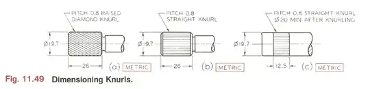
It goes on to specify that this is enough information for hand gripping purposes, but if the knurl is intended for a press-fit, a minimum diameter after knurling should be listed. This insures that there is enough upset formed by the knurling process to assure your press-fit is secure. In this situation it is obviously also important to include the toleranced diameter of the part before the knurl is applied.

I would not recommend calling out the depth of the knurl. The machinist will likely have to adjust this as it is the only option they have to make sure the pattern aligns with itself on successive revolutions. At the most, I would specify a minimum depth, but not a target depth or a maximum depth.

As a matter of style, I would recommend calling out the knurl on the face view, not the end view so it is more clear what it references. Additionally it may be hard for a machinist to knurl right up to that shoulder on the right of the knurled area. If you could hold the knurling back even 1mm that would probably help. You can probably safely assume that the machinist will know to only knurl the cylindrical faces, not the flats.

In the US, ANSI B94.6 has a tolerance class system to ensure that the pre- and post- knurl OD tolerances are compatible, but I haven't seen any reference to how it handles metric units like you have.

You can find a little more information on knurls and how they are calculated and formed in the Machinery's Handbook machining section, but it is very inch-centric.

Ethan48
  • 4,561
  • 19
  • 42
4

The (European) standard for knurls is DIN 82. The standard includes a proposed drawing representation as well. Its intention is to describe hand gripping aid knurls. As Ethan48 says, for fitting you need a more precise definition, at least for the outer surface (diameter, cylindricity, runout, etc.)

One remark to your design: look for knurling tools on the net, you might need some distance between the knurling and the shoulder.

enter image description here

2

Because I am not sure what are the standard dimensions of the knurl I made this kind of defining and sent to supplier, hope they will advice if something is not clear enter image description here

Stenly
  • 81
  • 1
  • 1
  • 3
-1

Knurls are usually made by rolling or cutting. A tool with a free-spinning rotating head (or opposed pair of heads) is pressed into the part on a lathe and the pattern is transferred (in negative) from the head.

So the pattern itself is fixed by the design of the tool head so you need to specify the tool type which gives you the pattern you want. Specific tool manufactures will have their own conventions for naming/specifying patterns.

Typically knurled patterns will be either straight (ridges parallel to the long axis of the part) or a diamond pattern (ridges crossing at 45 degrees).

Cut knurls tend to be a bit crisper than rolled ones but have some limitations on how they can be applied ie the tool needs to be advanced axially from one end of the knurl as opposed to rolling where the tool is advanced radially.

Chris Johns
  • 15,326
  • 3
  • 24
  • 42