7

I am working on an indirect ammonia chiller that is used to cool the ice in an arena. The system consists of 3 reciprocating compressors, an evaporative condenser with a vfd on the fan, a float throttling valve and a plate heat exchanger acting as the evaporator.

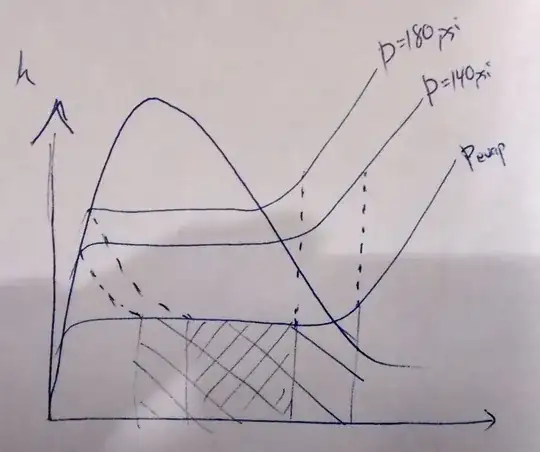
With one compressor operating, the condensing pressure of the ammonia ranges from 140 psi to 180 psi depending on the speed of the fan. When the condensing pressure is higher, the compressor is doing more work. When the fan speeds up, the head pressure lowers which corresponds to a drop in compressor work.

I know that lowering the condensing pressure reduces compressor work and am familiar with the pressure-enthalpy chart that is used to describe the refrigeration cycle. My question is, how does increasing the fan speed cause a drop in compressor work? The fan kicks on and rejects more heat from the gas, but what is the process or mechanism that occurs as you follow the refrigeration cycle that results in the compressor lowering the condensing pressure?

Air
  • 3,211
  • 4
  • 26
  • 47
Prevost
  • 307
  • 1
  • 5

2 Answers2

1

I think @regdoug is on the right track, but this is how I think of it: The work done by the compressor is equal to the difference in enthalpy of the ammonia between the compressor inlet and outlet; $W_c=H_{out}-H_{in}$ On the following pressure-enthalpy diagram, points 2 and 3 are the states at the compressor inlet and outlet, respectively:

enter image description here

Now, if the fan speed in the condenser is increased, it will draw more heat out of the ammonia, which will cause the temperature and pressure of the ammonia in the condenser to drop. Consequently, the enthalpy of the ammonia will also drop, as indicated by the dashed line in the pressure-enthalpy diagram (points 3' and 4'). Lower outlet enthalpy of the ammonia results in less work done by the compressor, according to the previous equation.

By the way, the other points in the diagram are as follows:

1->2 Evaporator

2->3 Compressor

3->4 Condenser

4->1 Throttle

Carlton
  • 3,064
  • 2
  • 15
  • 28
0

EDIT: I still think that I'm on the right track, but I have realized some errors that I made (specifically I have drawn my diagram with the wrong area shaded for work, I labeled the diagram h instead of T, and I skimmed over the specific volume ratio of the compressor) so until I get this straightened out, consider the answer as tentative at best.

As far as I understand, it works as follows:

  1. By increasing the fan speed, the heat rejected by the evaporator is increased
  2. The increased heat rejected can only be accomplished by "widening" the points on the evaporation line
  3. The increased quality at the output of the evaporator causes the compressor to compress to a lower pressure.

That may not be right, but it seems to make sense on the diagram I drew.

Vapor-compression refrigeration cycle

regdoug
  • 1,167
  • 6
  • 13