4

The crux of a PID controller is:-

output = Kp * error + Ki * integral + Kd * derivative

So typically there is proportionality and a continuously varying (analogue) output. In the case of a simple process like a domestic gas boiler, the boiler is either fully on or fully off. Or, say a cooling fan that can only be switched on or off to keep something cold.

In these cases, can a PID controller be used at all? There is still an error term. Or would an alternative form of control be necessary?

Paul Uszak
  • 926
  • 1
  • 9
  • 20

3 Answers3

3

So typically there is proportionality and a continuously varying (analogue) output.

Correct. This could be an analog voltage or a digital value.

In the case of a simple process like a domestic gas boiler, the boiler is either fully on or fully off. Or, say a cooling fan that can only be switched on or off to keep something cold. In these cases, can a PID controller be used at all? There is still an error term. Or would an alternative form of control be necessary?

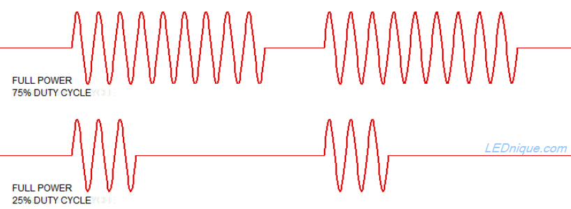
It certainly could and is in many industrial control systems. Heating, for example, is very often controlled in this way using variable duty-cycle where full power is applied for a varying percentage of a fixed cycle time. This makes the power control system a simple on-off type which can be implemented using relays or SSRs (solid-state relays).

enter image description here

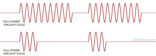
Figure 1. SSRs (solid-state relays) allow rapid switching while allowing varying duty cycle for heating loads. Source: Opto-triacs, solid-state relays (SSR), zero-cross and how they work.

The duty cycle is determined by the the thermal response of the system. A room heating system may have a response time in tens of minutes so a long duty cycle (several minutes) may be appropriate. On the other hand, a heat sealing station for welding plastic films together may have a response time of seconds and a duty cycle of a second or two may be appropriate.

If programming this control in a PLC the standard approach would be to use two timers.

  • Timer 1 is the period timer. Let's say it's set to 5 s.
  • Timer 2 is the duty cycle timer. If the PID output is 25% then Timer 2's timeout value is set to 5 × 0.25 = 1.25 s.
  • The output turns on at the reset of the period timer (Timer 1) and turns off when the duty cycle timer (Timer 2) reaches its timeout value.

    T1  
+--|/|--------[T1 5000 ms]--
| 
|   T1
+--|/|--------[T2 1250 ms]--
|
|   T2            HEAT 
+--|/|------------( )-------

Figure 2. Pseudo PLC code.

  1. T1 runs and when it reaches 5000 ms it is energised, cuts its own feed and resets. The timer starts again.
  2. T2 resets every time T1 does and its is energised after the duty-cycle delay.
  3. The heat turns on until the duty-cycle timer is done.

Relays can be used for switching but when the switching period gets down below a minute or so mechanical wear becomes a problem. SSRs solve the wear problem as they are solid-state and have no moving parts. Zero-cross types also eliminate both audible and electro-mechanical noise from the switching. (All the on periods in Figure 1 start on a zero-cross.)

Further reading:

Transistor
  • 12,108
  • 2
  • 22
  • 32
1

I was looking for a similar question and found this entry. So Transistor answer is right and give me all the hints to implement a version of this in Structural Text.

I am using a cross by zero SSR for my heating element and PT100 for temperature measurement. Control for my application is having a delta of temperature of +/-0.3C. I use my own PID equation from C for MCU. A minimum 2 seconds for switching was placed to avoid fast switching of SSR. The system usual set temperature is 45C but the PLC reads 450 as the temperature to include a decimal point. Find the code below. Hopefully this helps others:

MeasureDelay(IN:=TRUE,PT:=T#1000MS);
error:=SetTemperature-Temperature;
IF MeasureDelay.Q THEN
    MeasureDelay(IN:=FALSE);

cumError:= cumError+error * 1;//T#1000MS IF cumError<-100 THEN cumError:=-100; END_IF IF cumError>100 THEN cumError:=100; END_IF rateError := (error - lastError)/1;//T#1000MS

output := LREAL_TO_INT(1.5 * error + 0.7 * cumError + 5 * rateError);

lastError:= error; END_IF IF output>300 THEN ControlPort:=TRUE; ELSIF output<0 THEN ControlPort:=FALSE; ELSE time1:=DINT_TO_TIME(output100); IF time1<T#2000MS THEN time1:=T#2000MS; END_IF time2:=DINT_TO_TIME(30000-output100); T1(IN:=TRUE,PT:=time1); IF T1.Q THEN T1(IN:=FALSE); T2(IN:=TRUE,PT:=time2); IF T2.Q THEN T2(IN:=FALSE); ControlPort:=TRUE; ELSE ControlPort:=FALSE;

    END_IF

END_IF

END_IF

Fred
  • 9,782
  • 13
  • 36
  • 48
0

Yes, a PID controller does not know of the system it is controlling. It is perfectly fine to turn the control signal to binary on/off that is beyond the scope of the controller itself.

What the system does is unknown to the PID. There might be some lag, some predictive component or anything in the system between it and the controller. So even though its a PID controller does not mean it has to controll what you think is obvious. Hell, the PID may be inside or control another controller**.

Second, the description of PID allows for many implementations to occur. The formula above is more a abstraction instrument, to categorize rather than a this is how you implement a PID*. A lot of things are PID controllers even though they may do the terms differently than the formula says. For example the integrative term may just be a history dependent term, nowhere does it say it has to integrate the error over the lifespan of the machine. Instead it may be a time limited slice too implemented like say a running average. The values may be capped and have some of the later systems features reduced into them.

* Although, since you can abstract to this then you might as well use it as a guide to implement. But then many things are PID controllers implicitly like spring/shock absorber systems and hydraulic pistons.

** So while one can be tuning a PID, does not mean the entire overall controller is a PID

joojaa
  • 3,691
  • 1
  • 17
  • 31