I am looking to use FEA (specifically, Creo Simulate) to re-create the results of a static strength test on a part my company will be testing in our lab. Because the lab results are the ones we will be using to determine the utility and capability of the part, I'm doing this mostly as an exercise, to strengthen my FEA skills and to see how close to reality I can get the results of the analysis to be.
For a couple different reasons (write access to model files, investigation of the bolt functionality of Creo, more realistic application of load) I am attempting to model part of the test stand in addition to the part of interest. The part itself has a flange with a bolt pattern as part of its design, and we are using that bolt pattern to attach it to an adapter. The adapter will attach to the output of the motor, with the torque being applied through a key that sits between the adapter and the motor output.
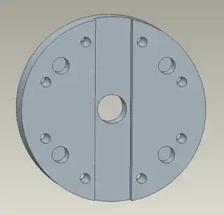
Below I have a picture of the keyway in the adapter for clarity. The part of interest is attached to the back side of this adapter, the key fits along the entire length of the keyway, and the adapter connects to the test stand output using the four larger bolt holes (these don't transmit any significant torque, they simply keep the assembly together.)
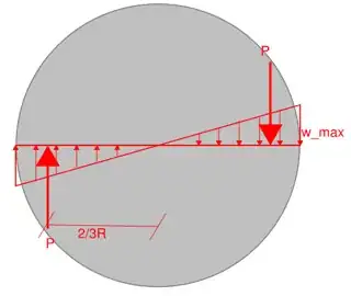
My issue is determining how best to model the applied load on the walls of the keyway. My intuition tells me that the load will vary along the length of the keyway, as what we're really applying is a torque that gets distributed throughout the key.
Given that $T=r \times F$, I'd expect there to be an inverse relationship between the force I should apply and the position along the keyway at which I apply it. Does the fact that this line of action is not radial complicate things?
In addition, I have two coordinate systems defined, the standard Cartesian, and a cylindrical one with the z-axis going through the center hole of the adapter as you might expect. Will applying the load in one coordinate system or the other significantly alter the result, and is one preferable? Will the distributed force equation be easier to define in one coordinate system?