12

Background

standard thermal furnace

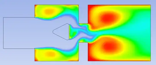
This is the standard design for a thermal furnace used in the Clauss process, which converts H2S to SO2. The main problem with the furnace is that gas mixing is rather poor and results in only a 60% conversion rate. This in turn increases downstream equipment costs to handle the impurities. A design improving the mixing of the gases is highly sought after.

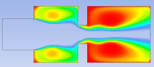
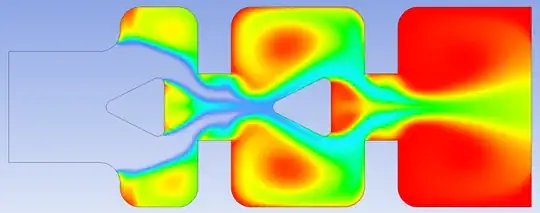
H2S and O2 is fed separately into the reactor. The combustion reaction starts and increases temperature to about 1400 °C. The choke point in the centre of the reactor is there to force the gases to better mix on either side of it.

What I have done thus far

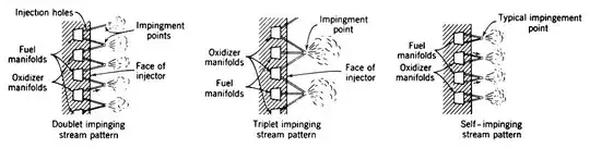
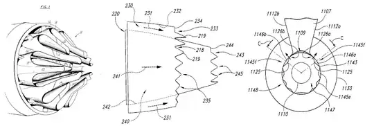
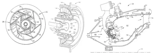
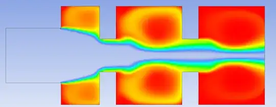
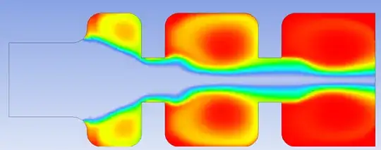
I have a design modification on the injectors that allowed much greater mixing, with inspiration taken from fuel injectors in motor vehicles.

modified injectors

I did not include the choke point in this drawing. It was merely done to test the validity of the concept.

The twice-angled injectors provide horizontal as well as radial velocity to the inlet gases. This causes a swirling effect on the fluid, improving mixing by about 60%. Mixing is here defined as the homogeneity of the outlet product distribution.

The advantages are two fold: The gas particles need to travel further due to the swirling, increasing the time they stay in the reactor. Thus, a larger conversion is also achieved, or viewed from a different perspective, a smaller reactor is needed to achieve the same conversion as the standard unit, dramatically reducing costs.

The question

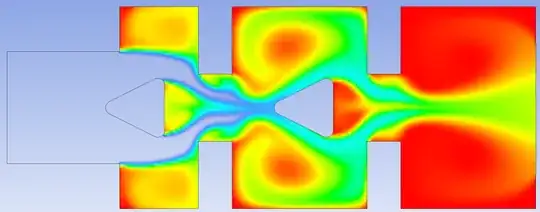
I wish to exploit certain fluid dynamics phenomena to improve upon the mixing. Eddy formation, for example, is used in the choking section. What else can be done to improve mixing? What features can be added/removed?

PS: Explain your proposed design in words, no need for actual modelling.
Of course, it would help me to see the idea, but it is not necessary.

I have access to Fluent in which I simulate these designs and compare them to the standard unit.

I am still eager to see what you can come up with.

22134484
  • 331
  • 1
  • 7

3 Answers3

5

As far as I understand your question you are looking for a way to diffuse/mix two gases into each other. The process is very hard to simulate "correctly" because of the characteristics of the equations. However, it is quite unlikely that you will have a worse mixing than predicted because the models usually underestimate the turbulent mixing processes. Your biggest problem could be the pressure loss connected to the turbulent mixing depending on the operating pressure of your system.

The good thing is mixing is needed in a lot of applications maybe you can get some ideas:

NASA investigated a lot of impingement mixing processes for their liquid-liquid combustion-chambers: Nasamixing

GE, Pratt, and Rolls-Royce have investigated the most efficient way to mix bypass and core-flow of their jet-engines: enter image description here

And finally flying and stationary gas turbine manufactures have experimented a lot to come up with a very efficient (fast) way to mix air and fuel: enter image description here

Basically, the idea behind all the examples is to increase the surface of the two fluids. On a molecular level the mixing/diffusion itself can only be increased by increasing the temperature. So at a given temperature mixing can only be increased by increasing the mixing-surface and let the molecular happen on a bigger scale.

However, especially shear-layers and swirling flows which are used in the last example are very hard to simulate because the turbulence models often do not capture the physics good enough.

A short summary or comment to your question:

I wish to exploit certain fluid dynamics phenomena to improve upon the mixing.

There is only one basic phenomenon of mixing and that is diffusion. In order to increase the mixing while having a constant diffusion is by increasing mixing-surface-area which is done most efficiently by swirling shear layers.

rul30
  • 1,202
  • 10
  • 24
4

Preliminary results

I added a conical structure before the choking point to separate the flow. Basically cutting the fluid. This cone is attached with 4 supports. This configuration increased mixing by a ridiculous amount. I achieved a near linear product distribution. However, I have not run temperature or structural analysis on this cone to validate whether or not it can with stand the temperatures or load applied to it. This cone was added to the standard structure. Further analysis should be done with the cone and twice angled injectors.

A sinusoidal wall was added to furnace to aid in Eddy formation on the boundaries. This increased the linearity of the product distribution, but lower the conversion rate, which I do not understand at the moment.

To aid in the modelling process, a simpler reaction is used. Benzene and oxygen is fed into the reactor at 600 Kelvin.

The legend off all of the following images range from 0%(clear) to 100%(red). All scenarios that were run, used exactly the same operating conditions and the overall length of the reactors stayed constant.

The resulting conversion looks as follows:

Standard

The resulting average conversion at the outlet was found to be 40.09%.

With the addition of the conical structure, the conversion increased to 43.43% and looks as follows:

Cone

A major improvement in conversion was seen when two choke points were added. The conversion that was found: 78.46%. Which is almost double compared to the standard reactor.

Double Choke

The next iteration, involved adding rounded features to the reactor. This resulted in a final conversion of 78.57%, which is not a large increase by any measure. But, it can be cheaply done.

Double Choke Fillet

Two cones where added into the double choke design so that the geometry of the cone may aid in eddy formation in the compartments. The result was as expected, and a conversion of 85.35% was found.

Double Choke Double Cone

The previous design was modified with rounding similar to that of a previous design. This resulted in a conversion of 86.71%

Double Choke Double Cone Fillet

These experiments of mine show that there are improvements to be made to this archaic design (literately, it came from the early 90's) by exploiting certain phenomenon.

I am currently in the process of combing the double choke, double cone, rounded design with the twice angled injectors.

Air
  • 3,211
  • 4
  • 26
  • 47
22134484
  • 331
  • 1
  • 7
1

rul30 put it best:

Basically, the idea behind all the examples is to increase the surface of the two fluids. On a molecular level the mixing/diffusion itself can only be increased by increasing the temperature. So at a given temperature mixing can only be increased by increasing the mixing-surface and let the molecular happen on a bigger scale.

One way to do this are static mixers. A static mixer is a series of blades, typically helical, that are inserted in a pipe. The blades will 'cut' and turn the fluid so that different volume elements are in contact.

You will, however, not be able to model one in 2D. There are different types - Helical:
Helical statix mixer
X Element:
X Element Statix mixer
and others.

Picking the right mixer is probably a science in itself, at first glance I only found articles about their use in adhesives production - these mixers are often used in liquid-liquid and liquid-gas application. This page advises yet another type for gas-gas application, a corrugated plate type. Static mixers for gas-gas mixing are also used in exhaust gas treatment, this could be one avenue of further research.

Pictures: Schumacher Verfahrenstechnik

mart
  • 4,811
  • 2
  • 19
  • 32