4

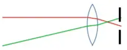
I'm planning to build a laser shooting target. Something like this:

In the long term I want to build something advanced like a professional grade target, in which the user is able to tell exactly where was the shot, but for now I'd be happy with a basic one like in the image.

Basically whenever a laser shot hits the black area it counts as a shot inside. I'm just unsure about how can I do it since I don't want it to easily confuse a shot with regular light, and if possible I would like to use optics side-effects to avoid cross-shooting (whenever one shoots someone else target, while misaligned with it).

To begin with, one has to be 10 meters away from the laser target, with a variation of a meter at most. The targets are held at a meter and a half high. The laser of a gun, in conformance with the regulations, has a ~3 mW peak during 15-20 ms of activity. The black area is about 7 cm in diameter.

I don't know the official specifications for a laser target in terms of light, but I found a brand with the specifications of one target (end of the page). It states "Sun resistance: 70k Lux." Does that mean that it is able to distinguish a laser shot from the ambient light at up to 70k lux ambient light? What is a simple way to understand the amount of light that represents?

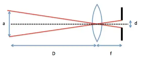
My idea so far its having a photo sensitive transistor in a PCB bolted to the back of the target. An aluminium sheet in the front with a circle in the middle of it, and a smoked acrylic sheet in its back (to fill the circle). And either a fresnel or a biconvex lens right next to the acrylic.

Both the biconvex lens and the acrylic converge the frontal light to a point (the point where the photo transistor stays), so that spot becomes mostly light coming exactly from the front of the target, and becomes sort of immune to most ambient light (since it will refract to the points around the transistor).

The problems I see so far are:

  • Which one (fresnel/biconvex) has the shortest light converging point?
    (I would prefer the target as slim as possible)
  • If one shoots the edge of the valid area, it's not a straight shot. Assuming one is perfectly aligned with the target, and the weapon is at its height, it would already become a ~90.2° incision. Being a little misaligned (half meter) and being half a meter lower than the target while shooting the center would represent a ~90.4° incision. Being misaligned and shooting the edge opposed to the misalignment direction would be an even more tilted shot. Is that little tilt enough to make the lens focus out of the transistor? It seems like a really small deviation.
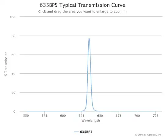
  • Is it worth it to get a sheet of red cellophane between the acrylic and the transistor? It would filter the non-red light, wouldn't it?
  • To avoid counting lights turning on or a cloud passing by as valid shots, can I can count 30 ms from the moment in which the light peak happens, and see if it has disappeared?

So basically the main question is:

Would either of these two lenses solve my problem, by converging the light coming from one direction into one point? Would it be practical? Are there better alternatives (like leaving the transistor alone without focusing; mirrors; etc.)?

EDIT: Floris guess was probably right. The signal seems to be modulated. I managed to have a shot at the spec sheet of one of the guns: 
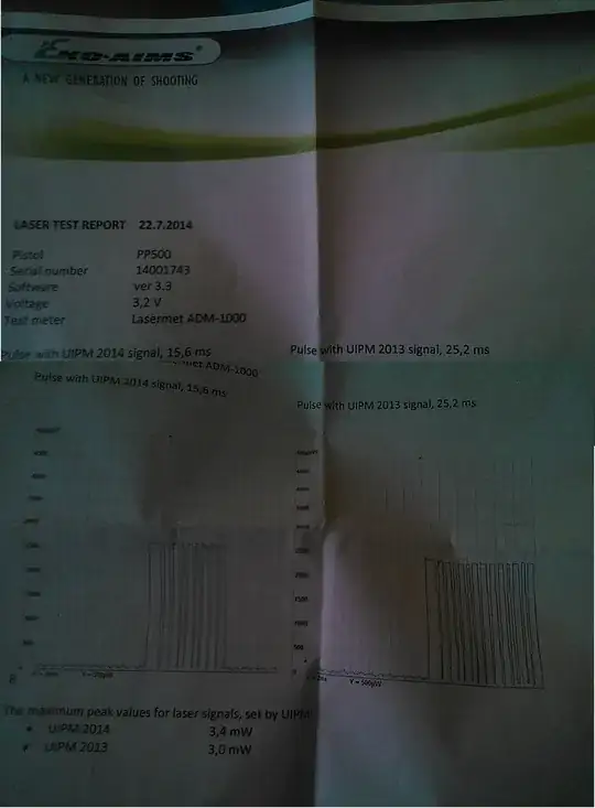
Those graphs mean that with UIPM 2014 signal it pulses 10 times in 15.6 milisecs? Should I get my target also recognising those pulses? I bought a BH1750FVI light sensor module, can those kind of sensors recognise differences of light in fractions of miliseconds? EDIT2: 
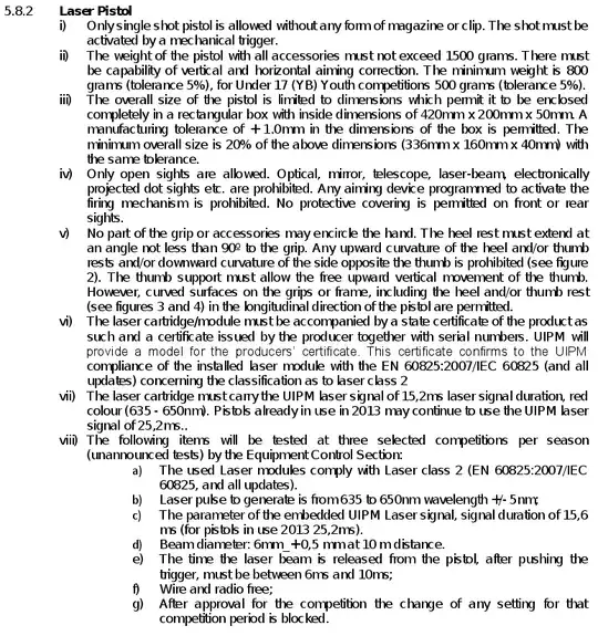
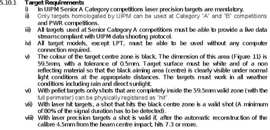
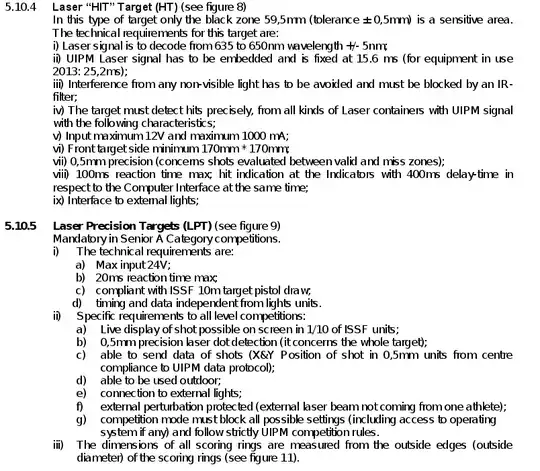
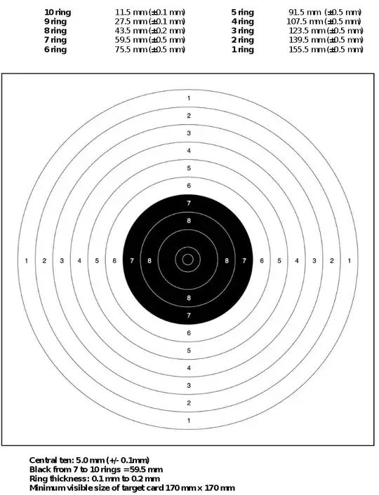
Found the official regulations: Regulations Regulations Regulations Regulations

Together with what was already answered, it should be enough to help anyone with the same question.

SOMN
  • 151
  • 5

1 Answers1

5

Briefly:

The way to distinguish your signal from any others (and incidentally get a massive gain in signal to noise ratio) is to use modulation. The simplest modulation scheme just turns the laser on and off very quickly (a few MHz) and your detection circuit (synchronized with the switching of the laser) ADDs detected signal when the laser is on, and SUBTRACTS when the laser is off. This is the principle of lock-in amplifiers. You can build a simple one with cheap CMOS switches, and they are incredibly effective. Any signal not at the "detected" frequency will be sometimes added and sometimes subtracted - so averaging over a few 1000 cycles it will be reduced to almost nothing.

Filtering light from wavelengths you are not interested in helps as well - this is why your IR remote has a dark red window, for example (on the receiver as well...)

Further thoughts

Having read your question again, and in light of the comments below, here is a bit more detail.

In general for a situation like you describe (where you want to detect a "signal" (the laser hit) in the presence of "noise" (the other guns, ambient light, the sun...) you have to look for the ways in which one signal is different from the others. This comes down to three things:

  1. Spatial difference
  2. Wavelength difference
  3. Temporal (modulation) difference

Let's take each of these in turn.

Spatial difference

You know roughly where the gun is positioned that is pointing at the target. We can use that to eliminate "cross fire". Let's look at this figure:

enter image description here

As you can see - if you have an on-axis aperture near the focal plane of your lens, then light that comes in off-axis will be rejected. How big that aperture needs to be follows directly from the geometry of the target - shooter - neighbor configuration. You already said your shooter would be approximately 10 m ± 1 m from the target - and if you are trying to keep the target "thin" (maybe a focal length of 20 cm) the focal plane would be very close to the focusing distance of the lens: $\frac{10\cdot0.2}{10-0.2}=20.4 cm$.

The angle subtended by the aperture at the center of the lens will be the acceptance angle - any lasers shooting outside that range will be blocked by the aperture:

enter image description here

Now for the choice of lens. A (plastic) Fresnel lens will be thinner, lighter and cheaper than another kind of lens - and sufficient for this application. They don't suffer much from spherical aberration, so it is possible to have a relatively large lens with a short-ish focal length. These may be hard to find, but I found a very cheap 7"x10" lens. You could cut it to size and stack two or three on top of each other to give you the focal length you need (the shorter the focal length, the thinner the target; but otherwise there is not much reason to spend the money, certainly for a proof of principle). If your target area is only 38 mm, there is a cheap 50 mm biconvex lens available on the same site: http://www.teachersource.com/product/biconvex--biconcave-lens-sets/light-color . Disclaimer: I am not associated with this site or the products.

General note about lenses: fresnel is thinner (and often cheaper) than conventional; little to be gained in this application from plano-convex vs biconvex (although plano would allow the front of the target to be flat).

Wavelength difference

Lasers are "monochromatic", meaning their energy covers a very narrow range in the spectrum. This means that if you have the right filter, you can block a lot of "non-laser" light. The narrower the filter, the better the relative blocking. For example, you can get a 635 nm filter with 5 nm FWHM - that's centered on a "better" red laser pointer.

enter image description here

That will cut out an enormous amount of external light - if you imagine (for estimating) that sunlight is uniform between 400 and 800 nm, then cutting out everything that is not within 5 nm of the laser cuts the sunlight contribution by 80 x ($\frac{5}{400}$). It would be expensive - but shows it can be done. How well your "red acetate sheet" will work is something you would have to experiment with...

An important reason to consider a filter is saturation: in the next step we will look at modulation, but that can only work if the detector is still linear over the range of intensities that are incident. If the detector (or electronics) are saturated, there will be no change in signal when the input intensity changes - so you would not be able to detect the small signal on top of the large one. By filtering "a good chunk" of the sunlight out, you make the system less sensitive - reduce the need for a massive dynamic range.

Modulation

The final point - and the one I started this post with - concerns modulation. In its simplest form, you can look for a sudden increase in intensity. For example, if you put a high-pass filter (series capacitor, shunt resistor) on the output of your photocell you would only see a pulse if the intensity suddenly increases. This would happen with a laser pulse, but not with sunlight. You could feed that signal into a comparator, and it would detect the pulse.

More complex systems could use pulse modulation - you can learn about this, and get kits for very little money, from https://learn.sparkfun.com/tutorials/ir-communication . The problem with the transmitters on these systems is that throw a wide beam (so you don't have to "aim" at the TV). Replacing them with a narrow beam transmitter (like a laser diode) you should be able to re-use most of the other components. This would allow you to use several guns (each programmed with their own "code") and tell them apart.

But as I mentioned earlier, the really cool system uses a lock-in amplifier scheme; using a cheap quartz oscillator you should be able to detect the signal regardless of phase (derive the quadrature signal from the oscillator and have two detection channels; then add the square of these signals together to have intensity independent of phase). As long as your detector does not saturate, this method is incredibly sensitive: it used to be one of my favorite optics demonstrations to show how you can "see" a small LED light up from across the room when the oscilloscope shows "nothing but noise". There is a nice description in this article - especially part D.

Floris
  • 466
  • 2
  • 5