In addition to my original answer, I thought it worth adding an example of how you might model the full trombone. I noticed that in your screenshot you had "Plane 3" visible, indicating to me that you've been adding reference geometry outside of the three base planes?
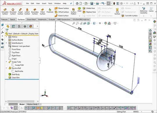
This model can be made using just two sketches and four features, with all of the dimensions within those sketches being exactly copied from the reference drawing in their positioning. This removes a lot of potential for error.
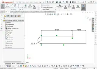
Step 1) Sweep path: I have taken the flared end to be the datum, and built a sketch following the path of the tube. The drawing is dimensioned to the centreline so this is easy to match.
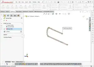
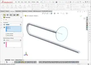
Step 2) Sweep body: Select the path, and Sweep a body. Select "Circular Profile" and enter in the outer diameter of the tube [I'm aware the drawing in in inches and my model is in millimetres - I didn't think it worth changing my settings just for this demo!)
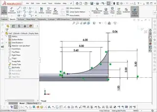
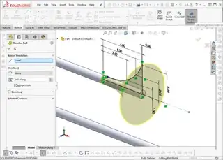
Step 3) Bell Profile: We covered this in the original answer. The only thing to add, is that I've set the left-most anchor point to be coincident with the tube surface. This means that if you were to edit the tube diameter that we set in Step 2, then this sketch would automatically update. This is where defining the curve of the bell as a parabola instead of with coordinate points would come into its own, as the whole curve would be able to adjust to accommodate the change. Note again how all dimensions are linked to the same datum that we picked before.
Step 4) Revolve Bell: Pretty self explanatory, revolve. It's best practice to put a centreline into your sketch, and SolidWorks should recognise this as the Axis of Revolution automatically.
Step 5) Shell Body - shell the body to the specified wall thickness.
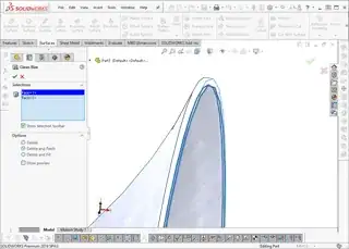
Step 6) Clean Rim: Because the drawing specifies that the rim has a horizontal external diameter, rather than being perpendicular to the spline, this meas that the shell command leaves a small 'step' on the inside of the rim. This is not an error - try reducing the wall thickness down to a smaller value to see where this comes from. Using the 'Delete and Patch' tool will remove these two faces, and extend the inner surface of the bell to meet the external diameter.
Step 7) Admire your work.