39

I recently visited a railway museum with a lot of Soviet-era locomotives. The picture below shows the wheels on a locomotive from the 1930s or 1940s. Some of the wheels are thicker on one side (as it it were a partially filled cup). What is the purpose of that?

Picture of the wheels of a Soviet-era locomotive

(Now that I am looking at the picture again I wonder if they are balancing the weight of the coupling rods in some way.)

Glorfindel
  • 279
  • 1
  • 5
  • 11
adam.baker
  • 501
  • 1
  • 4
  • 5

6 Answers6

55

Those are counterweights. They work exactly the same as those lead counterbalance weights on the wheels of your automobile.

If they left those out, then those connecting rods and bearings would create an out-of-balance condition, and the wheels would vibrate at higher speeds. That could very well damage the wheels. But as a couple of others have nicely pointed out, the violent shaking could derail the train.

Mike Waters
  • 785
  • 5
  • 11
31

Those are balance weights against the joints used for the rods linking the wheels together.

Solar Mike
  • 16,242
  • 1
  • 27
  • 33
16

The oversized counterweights on the second set of wheels are to help balance the additional inertia of the pistons, piston rods and crossheads, which are directly connected to the wheels on this axle. (In a former life I was a museum conservator and rebuilt, and operated, steam traction engines and a locomotive.) ronford

Ron Ford
  • 161
  • 2
7

These counterweights are found on all piston-driven steam locomotives (not just Soviet designs), and even a few types of diesel locomotive using connecting-rod drive. As other answers note, their purpose is to balance the weight and momentum of the connecting and drive rods, which would otherwise cause heavy vibration when running at speed, to the extent of lifting the wheels off the track.

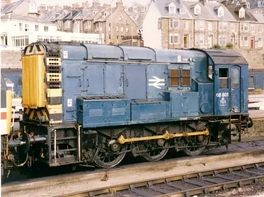
Here's a diesel example; the weights are relatively small here, but they can be seen on all three wheels to the lower left of the axle. On this shunting locomotive, the traction motors are connected to the front and rear axles, while the centre axle is driven through the connecting rods which also prevent any single axle from slipping under load.
BR Class 08 shunter

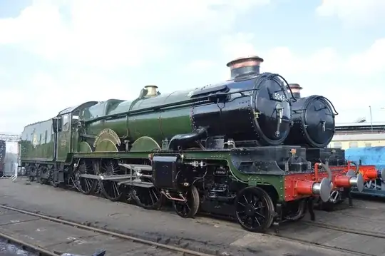
On this more elegant steam loco, designed for express passenger service, there are both strengthening webs on the crank side of the wheel, and balance counterweights on the opposite side. There's actually a second pair of cylinders between the frames, driving the leading axle, so the counterweighting is different for all three pair of driving wheels. Part of the counterweighting for the leading axle is built into the inner crank, rather than having it all on the wheels. Here you can also see that the carrying wheels on the leading bogie are not counterweighted, because they don't have any cranks.
GWR Castle

Chromatix
  • 171
  • 1
2

Slightly different answer - aside from the hammer effect of having out of balance connecting rods, there is also a different problem set.

Since the left and right hand rods are at connected at 90 degrees wrt each other (deliberately, as this is how you avoid the dead center starting problems referred to above), what happens is that as they rotate, the whole engine starts to sway from side to side due to the unbalanced rotating load. If you happen to hit a resonant frequency with the rails, the engine (and train) can derail entirely. The faster you go, and the more driving wheels that the engine has, the worse the problem. 2-10-4 ("Texas"class) locomotives were notorious for having this problem, for example.

Finally, having one side 'pushing' whilst the other is 'pulling' can cause the axle boxes to work loose and this will severely increase wear on the axle boxes, wheels and brakes etc and in extreme cases, it can cause the loco chassis to fail (bend or even break) due to repeated flexing. Since both Berkshire (2-8-4) and Texas locomotives were designed to pull heavy freight loads, this can also cause the loco to 'fishtail' at any speed, which causes (different) problems again.

Rick

-2

These act similar to the flywheel of an engine, keeping the steam engine running smoothly, especially at the start of rolling when there is not much rolling momentum in the wheels.

They are positioned such that when the links are nearly expanded fully and there is a chance of wheel lock-up at the dead point, the gravity of the ballasts encourage the wheel to keep rolling and not lock up, or worse, back up.

EDIT

After some comments/ answers, I think a few points need to be clarified.

  • If these were meant to be just ballast for the wheels and counter the weight of joints or links attached to them, they needed to be installed off the plane of the wheel by the same amount as those links. Because as they are they create a considerable imbalance on the wheel if we look at the wheel's cross-section. A rotating wheel with an attached off-plane mass will not be balanced by adding weight in its plane; it will tend to turn about an axis which passes through the slanted axis of symmetry, therefore wobble.

  • The fact that they are elongated circular segments, as opposed to just a cylindrical shape similar to the mass of the links, helps them have greater angular momentum, hence additional rotational energy (parallel axis angular momentum: the sum of spinning momentum and rotation of CG about an axis momentum)

kamran
  • 23,517
  • 2
  • 22
  • 42