Post-tensioned prestressed concrete beams suffer from a multitude of losses. When jacked, they suffer friction losses and their tension diagram is, for example (to simplify the drawing, I'm using the linearized version of the friction loss equation here. It also goes without saying this is all horribly out of scale).
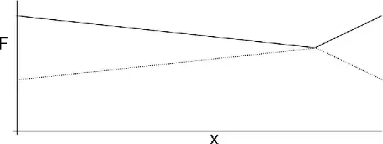
This diagram obviously represents a beam prestressed from both ends. Also, the cable's path is clearly non-symmetric, with the right side probably being excessively curved, while the left is probably far smoother. The dotted lines simply demostrate what the digram would be if the cable were prestressed from only one end.
When the cable is then anchored to the concrete, the anchorage slips into the concrete, causing losses. These losses, however, are limited by friction to an area around the anchorage since the cable has by this time already been grouted. We can define the point where anchorage slip losses end as $X$. An anchorage slip of $\delta$ is by definition equal to $$ \delta = \int\limits_0^X\Delta\epsilon_p(x) dx = \dfrac{1}{E_p}\int\limits_0^X\Delta\sigma_p(x) dx\\ \therefore A_pE_p\delta = \int\limits_0^X\Delta F(x) dx $$ where $x=X$ is defined as the point where the anchorage slippage losses end.
We therefore have a relation between the constant $A_pE_p\delta$ and the area between the force diagram before and after these losses. All we need to do now therefore is find $X$ such that the equality is satisfied. For simple cable paths there are some analytical methods, but they aren't relevant to this question.
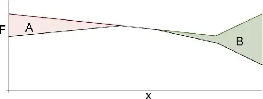
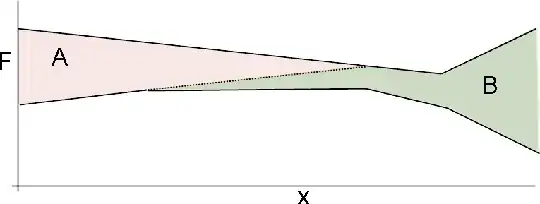
If the slippage losses are small enough, we just need to calculate the losses for each side, such that $A = B = A_pE_p\delta$:
That case, however, is quite simple. From now on, I am less sure of whether what I'm saying is correct, so please correct me if I'm mistaken.
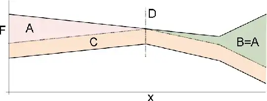
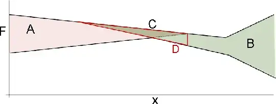
If, however, the losses are such that one side interferes with the other, it is easier to find an area $A+B+C = 2A_pE_p\delta$, where $A=B$, point $D$ is defined as the point where the losses first encountered each other and $C$ is simply a uniform loss along the entire cable that occurs once point $D$ is reached:
My first question is: is this a correct calculation of the anchorage slip losses in case the anchorages are released simultaneously? Is there a simpler (but generic) method?
The other question is what if the anchorage slippage losses are not simultaneous?
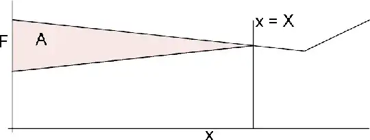
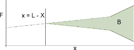
For the left side we may find $X$ and reach the following result, where the area $A = A_pE_p\delta$:
For the right side I'd consider calculating the losses on the friction diagram considering that the cable was only pulled from the right side, so we get the area $B = A_pE_p\delta$:
We can then throw that on top of the results for the left side and get the following, where $C$ is the area overlapping with $A$ and $D$ is the part of $B$ after the end of $A$ ($C$ is contained within $D$ which is a part of $B$):
So, what now?
Should the area $D$ be transposed to accompany the force profile after the left anchor settled?
Is this correct? Is there an easier (but generic) method to solve this case as well? Throughout this, I've made use of the assumption that the friction (and therefore anchorage slip) losses are linear, which they are not. Other than the mathematical headache of dealing with exponential equations, is there anything here that simply won't work using the losses' true exponential form?