4

I need help to check a calculation I did. I want to know if it is possible to use this method or if I am using an assumption which is wrong. Let me explain the problem, a beam with length $l$ is fastened in one end. A force $F$ an a moment $M_v$ is applied at the end of the beam, see figure below. The beam has a circular cross-section. Due to the force, the end of the beam will deform a length $\delta$. Only the deflection is known and the geometric parameters, such as the length and diameter.

Using Euler-Bernoulli beam theory the deflection can be expressed as:

$$\delta = \frac{Fl^3}{6EI} \tag{1}$$

Where $E$ is the Young's Modulus of the material and $I$ the inertia, which is $I=\frac{\pi d^4}{64}$ for a circular scross section. Here $d$ is the diameter of the beam.

Inserting the inertia in (1) and rearranging it as an expression of $F$ gives:

$$F = \frac{3 \delta \pi d^4 E}{32l^3} \tag{2}$$

This can be inserted in the general formula for maximum bending stress in a cross-section

$$\sigma_{max}= \frac{Fl}{\frac{\pi d^3}{32}} = \frac{32Fl}{\pi d^3} \tag{3}$$

Here the bending resistance for a circular-cross section has allready been inserted in the formula and the bending moment has been replaced for the maximum moment which is $Fl$.

This is the part which I am not so sure on, I use the force from (2) and insert it in (3) to get the maximum stress. Please let me know if this is possible or if I am making an error.

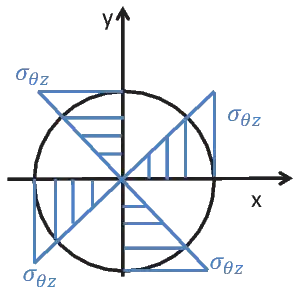
Furthermore, the shear stress can be calculated from $\tau = \dfrac{M_v}{W_v}$ where $W_v = \dfrac{\pi d^3}{16}$, which is the torsion resistance in the material. I then proceed to use the von Mises yield criterion to get an estimate of the maximum stress in the material.

$$\sigma_{von\ Mises} = \sqrt{\sigma^2+3\tau^2}$$

As I asked before, I am mainly interested if this is a possible way to proceed with solving this problem or if I am using some methods/assumptions which are wrong.

Beam loading case

Wasabi
  • 13,167
  • 8
  • 39
  • 62
loStraniero
  • 187
  • 8

1 Answers1

2

In general what you are doing is ok. Assuming you have small enough deflections (either through bending or torsional), you can independently solve the problems. I.e.:

  • Calculate the Force required to obtain the bending exactly as you have done. $$F = \frac{3 \delta \pi d^4 E}{32l^3}$$
  • Calculate the magnitude of the shear stress.

Caveats

However, from that point on there are a few caveats. Regarding:

a) bending: the maximum magnitude of normal stress you are calculating is at the top and bottom of the beam. Any point on the neutral axis should have a magnitude of zero.

b) torsional shear: The magnitude at the distance $\frac d 2$ is constant but the direction changes. see the following image:

Torsional stress at differet point of the crosssection1.

the magnitute of the maximum torsional stress is correctly:

$$\tau_t = \frac{M_u}{\frac{\pi d^3}{16}}$$

c) Shear: Although usually discarded there is also a shear stress associated with $$\tau_s = \frac{F}{\frac{\pi d^2}{4}}$$. Normally, that is very small, but also it has a constant direction (downwards in this occasion).

The point you need to take is that you need to add as vectors $\tau_s$ and $\tau_t$. Therefore, at different point in the material you'd have different values. Given image 1 and taking points A,B,C,D anti-clockwise, the resultant shear stress will be:

  • at the rightmost point ( Point A (+x, y=0) will be $$\tau_{A, res} = \tau_s - \tau_t$$.
  • at the topmost point ( Point B (x=0, +y) will be $$\tau_{B, res} = \sqrt{\tau_s^2 + \tau_t^2}$$.
  • at the leftmost point ( Point C (-x, y=0) will be $$\tau_{C, res} = \tau_s + \tau_t$$.
  • at the bottommost point ( Point D (x=0, +y) will be $$\tau_{D, res} = \sqrt{\tau_s^2 + \tau_t^2}$$.

Maximum stress

So the main thing is regarding your equation of the Von Mises. Which values do you plug for $\sigma$ and $\tau$.

You'd need to go through each point and apply the corresponding stress:

  • Point A, use $\sigma_{A} = 0$ and $\tau_{A, res} = \tau_s - \tau_t$
  • Point B (and D), use $\sigma_{B} = \frac{32Fl}{\pi d^3}$ and $\tau_{, res} =\sqrt{\tau_s^2 + \tau_t^2}$
  • Point C, use $\sigma_{A} = 0$ and $\tau_{A, res} = \tau_s + \tau_t$

Unfortunately, these are not the only points you need to check. For example, you should check at least at $\pm 135$ degrees (in that quadrature in the image $\tau_s $ and $\tau_t$ do not cancel each other). But that is the idea.

Wasabi
  • 13,167
  • 8
  • 39
  • 62
NMech
  • 24,340
  • 3
  • 38
  • 77