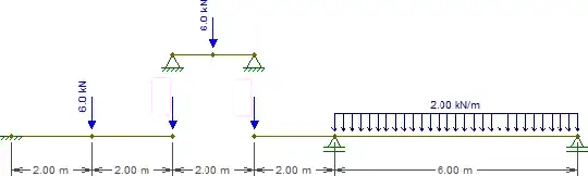
While this beam presents five constraints ($X_A$, $Y_A$, $M_A$, $Y_F$, $Y_G$), it is in fact statically determinate. A statically indeterminate structure is one where there are more unknowns (constraints, in this case) than there are static equilibrium equations. Usually one has three equations: $\sum F_X = 0$, $\sum F_Y = 0$, $\sum M_? = 0$ (where $?$ is any arbitrary point). Hinges, however, give us an additional equation each: $\sum M_{h\pm} = 0$, where $h\hspace{-2pt}\pm$ is one side of the hinge (left or right), such as in this question. This is different from the global null bending moment equation which considers all forces to either side of the hinge. Adding the two additional equations given by the hinges at $C$ and $E$ to the three global equilibrium equations, we therefore have as many equations as we have contraints (5), and can therefore solve this problem by the traditional means.
That being said, there is a much easier way of doing this which is entirely hands-on, without computational aides.
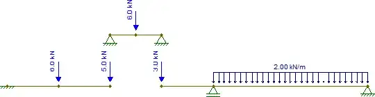
For this hands-on approach, one needs to observe the double hinge in the span $\overline{CE}$. This means that the bending moment at $C$ and $E$ must be null, much like with a simply supported beam (a more in-depth explanation of why this comparison is valid can be seen at the end).
So let's replace that beam with the following pieces (notice that the loads at $C$ and $E$ are left blank for now):
Solving the beam representing $\overline{CE}$ is trivial. For now all we need are the reactions, which are equal to $3\text{kN}$ at each support.
Now get those reactions and toss them down to the other pieces, remembering that at $C$ there is also the concentrated $2\text{kN}$ force, which must be added. We therefore have:
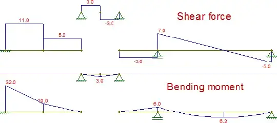
The other pieces are also isostatic and can be trivially solved (assuming one knows how to obtain internal forces of isostatic structures). The resulting internal forces are (I changed the support at $G$ just to make that piece stable for horizontal forces, which changes nothing in this case):
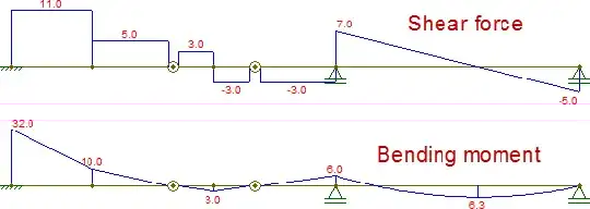
Composing these diagrams, they are identical to those obtained by the original beam:
A simple reason why the comparison can be made between those double-hinges and a simply supported beam is because this is the basic principle behind Gerber beams (which is basically what $\overline{CE}$ represents). They are beams which rest on other beams (see example here, where the beams to the right and left are Gerber beams) and which can therefore be "lifted" from the rest of the structure, solved, and then have their reactions distributed to the rest of the structure. One doesn't have to worry about the influence of external forces or the neighboring beams transmitting shear forces due to the fact that the bending moment must be null at each extremity of the Gerber beam. This means that the integral of the shear along the Gerber beam must be null, which can only occur if only the loads within the beam and the reactions at its extremities are considered.
The program I used for these diagrams was Ftool, a free 2-D frame analysis tool.


