I have inherited a DIY build and I have some doubts about its design. Have a look at the following diagram:
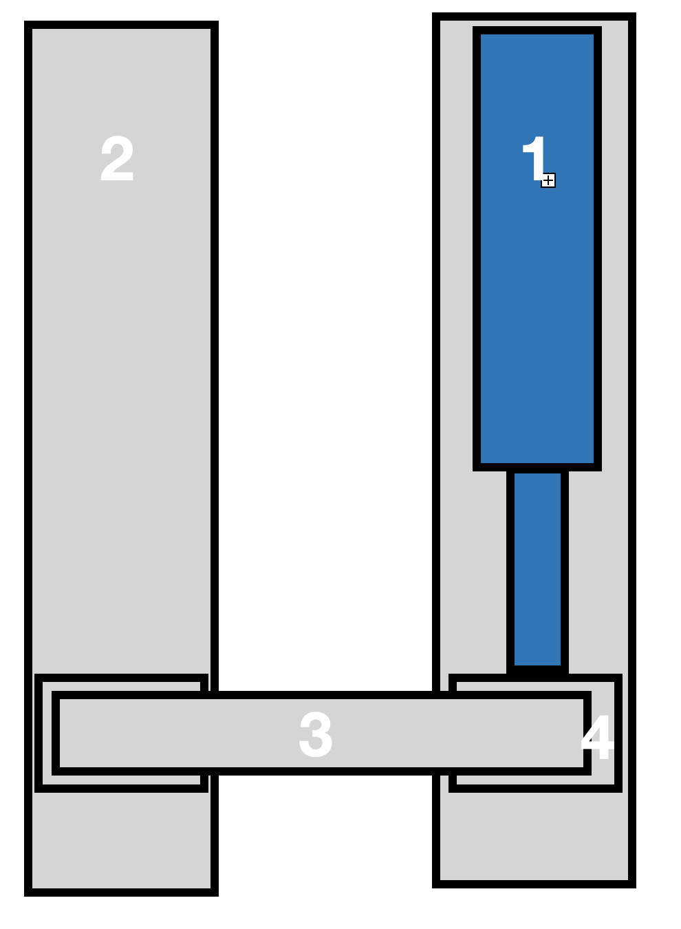
1 is the linear actuator. It's quite beefy 2000 lbs 12" stroke. It is installed in an aluminium channel. 4- Is a carriage, essentially a box section with little rollers on all sides, so it has no play within the channel and moves quite smoothly. This is connected to the actuator's rod. 3. Is a flat steel bar that links to an identical channel (2) and carriage assembly, though this doesn't have an actuator in it.
The system is supposed to lift a max 220 lbs load that is evenly distributed along the bar.
My questions are:
- While there don't seem to be any bending forces to the actuator itself, is it a safe design, as far as longevity of the components goes?
- is there anything I can do in channel 2 to support the system, e.g. a spring at the bottom, etc. to address any design problems?